 Tweet
Tweet
I just completed my suspension upgrade on my 66. I did a write up on a word doc but when I tried to paste it for a post, I got an error message but never stated what the error was. So I thought I'd break it up a little and post this. The main purpose of this post is to show you guys that if you have never done an alignment, don't be afraid to try. I had strayed a little bit from my original scope on my Mustang's suspension and realized with the components, it would be really helpful and save me a lot of money, aggravation and frustration. On my Mustang caster and camber are set by shims. Install more shims in the front A arm bolt and you add caster as well as adding positive camber which is what I don't want. The problem with early Mustangs is they have too much positive camber. My new suspension components from Street or Track offer lots of options in setting caster and camber. I did not install any shims initially since my UCA already have the rod ends adjusted for what I guess is about 3* positive caster. So follow along!
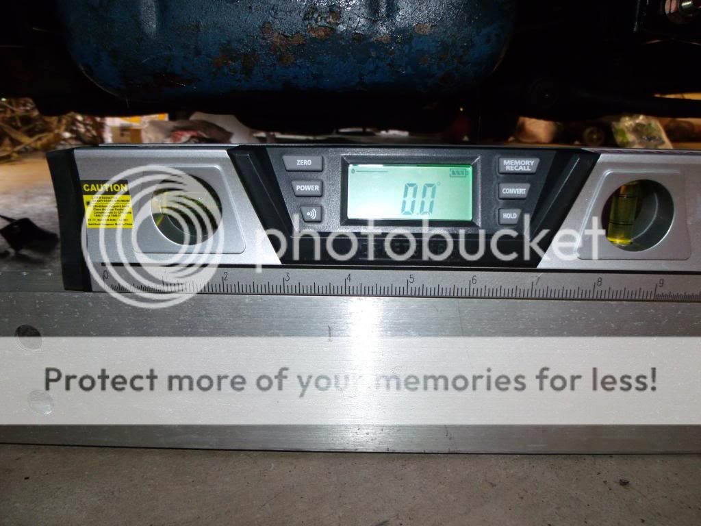
I was lucky, my floor was dead flat side to side. I used a piece of aluminum C channel that came from an old token ring rack and a digital level from Sears. I wasn't too worried about the floor being level front to back, I'll explain later.
Next, I needed a line on the floor parallel to the tires on either side. I used a piece of angle aluminum from the same rack. While not visible, I folded up 3mil, 55 gal contractor plastic garbage bags under each front tire to act as turn tables. Several layers of wax paper will work too.

My caster/camber gauge came Goracin off ebay but Longacre has the exact same one, same price just different color and name stamped on it. This is on my left wheel, it reads just a little more then 1.25* neg camber, roughly what I was looking for. My only complaint with the gauge is the bubble could be a little bigger. As it is, if I had exactly 1.25*, one edge of the bubble would be right in the middle of .75* and 1* and the other edge of the bubble would be between 1.25* and 1.5*.

This is the right wheel. originally I had 1.5* neg camber. I could have left it at this point and been fine especially since it's just a street car. More out of curiosity I wanted to see if I could do better. I initially tried a 1/64" shim but it didn't do too much so I pulled them out and installed 1/32" shims and got this. With in 1/8*! I'll take that. I should also note that at the end of the gauge is another bubble to make sure the gauge is level front to back.

You can see the shim I added

And here

Setting caster; First I have to apologize, I didn't get the whole image of the end of the gauge. The end is machined to a 140* angle. Now here's where that pencil line comes in. I turned the left wheel to the left. That 140* angle also means there are two 20* angles as well. So eye up the end of the gauge to the pencil line and there you have it. The wheel is 20* to the left. No need to have a degreed turntable that the alignment shop has. it's very easy to get the gauge exactly parallel to the pencil line. Now we set the gauge to 0* with the thumbscrew. Also make sure you level front to back the gauge with the bubble at the end.

Now turn the wheel to the right. Here you can see the end of the gauge line up to the pencil line on the floor giving me my 20* to the right.

And here I have 3.5* positive caster. Instead of playing with shims and having a catch 22 with camber, I simple adjust the front struts. Normally they are not adjustable on 65-66 but the ones I bought are.

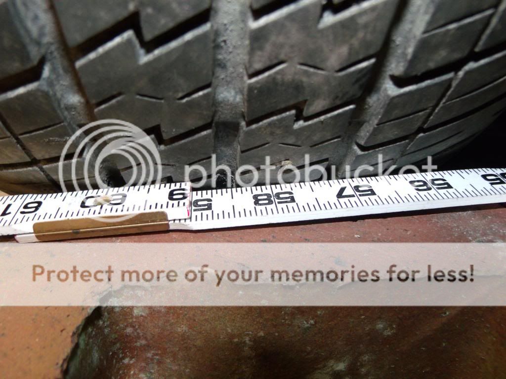
To set toe, I used two wooden folding rulers supported by bricks so the ruler wouldn't sag and altering the reading. I tried tape rulers but the end that's riveted had too much slop for my liking. I used the left wheel the starting point and used the edge of the tread. I didn't show the left wheel, only the front and back of the right to show readings. So we have a reading of 58 and 7/16".
Here's the back of the right tire, I got my 1/16" of toe that I was looking for by adjusting the sleeves on the tie rods. make sure you center the steering wheel first. I didn't have to hold the steering wheel with any straps.

Typically to increase or decrease toe, you're going to have to turn the sleeves in opposite directions. If the steering wheel is not centered, turn both sleeves equally in the same directions.
How did it come out? FANTASTIC! I was totally floored at how well my 1st time alignment came out. The car drives great Now I feel that I have learned something that I use to think was a black art. I can try different setting any time I want and know it was done right! I think any body who is doing their own suspension work even just replacing worn parts has the ability to do their own alignment. I hope you enjoyed my post.
FYI, my alignment specs are 3.5* positive caster, 1 3/8* negative camber and 1/16" toe in. I'm thinking of trying 5* caster. This is a manual steer with a 16:1 box.
I was lucky, my floor was dead flat side to side. I used a piece of aluminum C channel that came from an old token ring rack and a digital level from Sears. I wasn't too worried about the floor being level front to back, I'll explain later.

Next, I needed a line on the floor parallel to the tires on either side. I used a piece of angle aluminum from the same rack. While not visible, I folded up 3mil, 55 gal contractor plastic garbage bags under each front tire to act as turn tables. Several layers of wax paper will work too.

My caster/camber gauge came Goracin off ebay but Longacre has the exact same one, same price just different color and name stamped on it. This is on my left wheel, it reads just a little more then 1.25* neg camber, roughly what I was looking for. My only complaint with the gauge is the bubble could be a little bigger. As it is, if I had exactly 1.25*, one edge of the bubble would be right in the middle of .75* and 1* and the other edge of the bubble would be between 1.25* and 1.5*.

This is the right wheel. originally I had 1.5* neg camber. I could have left it at this point and been fine especially since it's just a street car. More out of curiosity I wanted to see if I could do better. I initially tried a 1/64" shim but it didn't do too much so I pulled them out and installed 1/32" shims and got this. With in 1/8*! I'll take that. I should also note that at the end of the gauge is another bubble to make sure the gauge is level front to back.

You can see the shim I added

And here

Setting caster; First I have to apologize, I didn't get the whole image of the end of the gauge. The end is machined to a 140* angle. Now here's where that pencil line comes in. I turned the left wheel to the left. That 140* angle also means there are two 20* angles as well. So eye up the end of the gauge to the pencil line and there you have it. The wheel is 20* to the left. No need to have a degreed turntable that the alignment shop has. it's very easy to get the gauge exactly parallel to the pencil line. Now we set the gauge to 0* with the thumbscrew. Also make sure you level front to back the gauge with the bubble at the end.

Now turn the wheel to the right. Here you can see the end of the gauge line up to the pencil line on the floor giving me my 20* to the right.

And here I have 3.5* positive caster. Instead of playing with shims and having a catch 22 with camber, I simple adjust the front struts. Normally they are not adjustable on 65-66 but the ones I bought are.

To set toe, I used two wooden folding rulers supported by bricks so the ruler wouldn't sag and altering the reading. I tried tape rulers but the end that's riveted had too much slop for my liking. I used the left wheel the starting point and used the edge of the tread. I didn't show the left wheel, only the front and back of the right to show readings. So we have a reading of 58 and 7/16".

Here's the back of the right tire, I got my 1/16" of toe that I was looking for by adjusting the sleeves on the tie rods. make sure you center the steering wheel first. I didn't have to hold the steering wheel with any straps.

Typically to increase or decrease toe, you're going to have to turn the sleeves in opposite directions. If the steering wheel is not centered, turn both sleeves equally in the same directions.
How did it come out? FANTASTIC! I was totally floored at how well my 1st time alignment came out. The car drives great Now I feel that I have learned something that I use to think was a black art. I can try different setting any time I want and know it was done right! I think any body who is doing their own suspension work even just replacing worn parts has the ability to do their own alignment. I hope you enjoyed my post.
FYI, my alignment specs are 3.5* positive caster, 1 3/8* negative camber and 1/16" toe in. I'm thinking of trying 5* caster. This is a manual steer with a 16:1 box.


Comment