Announcement

Collapse
No announcement yet.

Rebeldryver's '65 Impala SS Black Betty

Collapse
X
 
  • Filter
  • Time
  • Show
Clear All
new posts

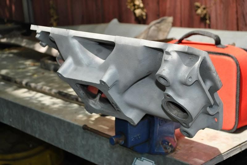
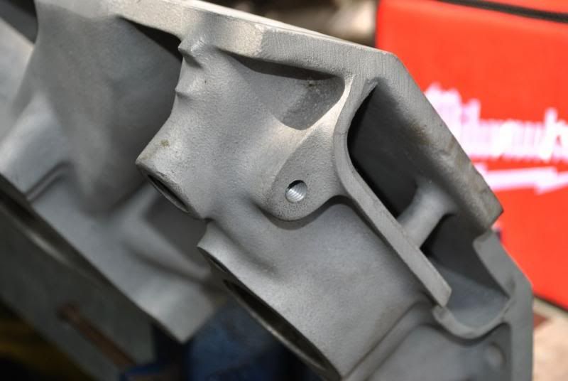
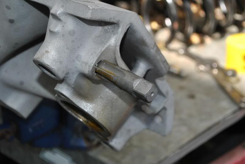
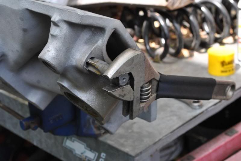
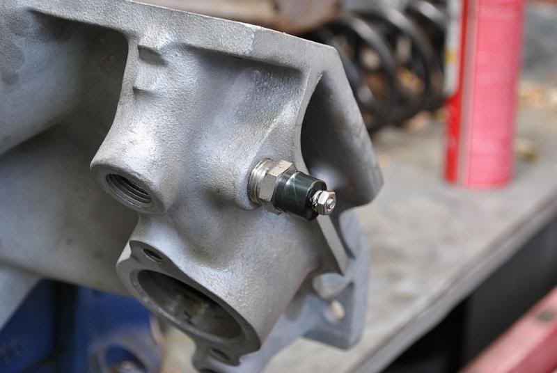
  • On the '76 4-bolt block in the yellow van, there is a place a sensor can go under/around the rear 2 sparkplugs on the drivers side.

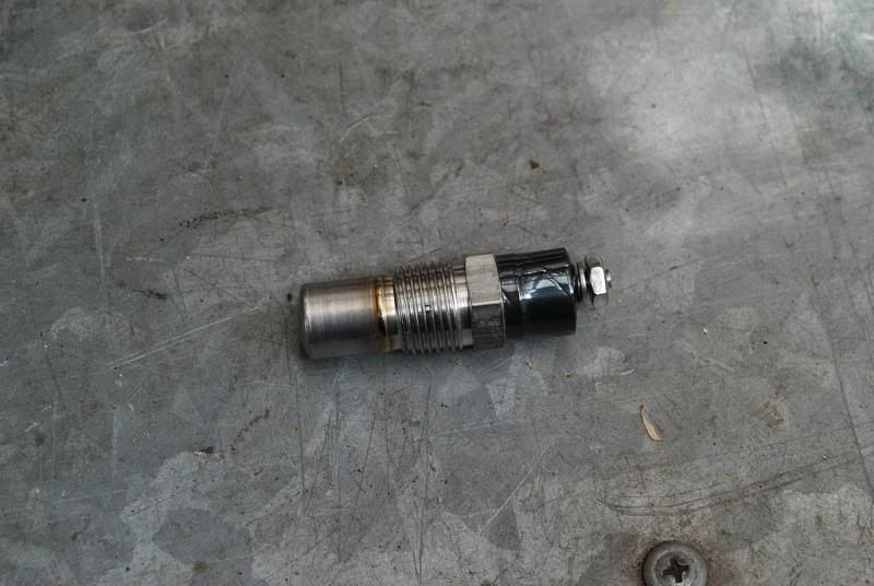
    I had my sensor in there when I first put it together, but it read "weird" and I moved it to the manifold.
    Of all the paths you take in life - make sure a few of them are dirt.

    Comment


    • Stock heads do have that place, but my Edelbrock heads do not.
      BS'er formally known as Rebeldryver

      Resident Instigator

      sigpic

      Comment


      • Here's the fuel pump with it's vacuum port and some JB Weld for extra sealing and strength. I put a vacuum cap on it for now.


        This is my Aeromotive fuel regulator, part #13301. I like this one as it can be run with a return line or dead head. It's boost referenced and will run at 20 lbs of pressure to do so. It also comes with a second spring to run as high as 70 psi for efi. Yes DG, I am thinking ahead.

        Last edited by Scott Liggett; April 9, 2013, 09:57 AM.
        BS'er formally known as Rebeldryver

        Resident Instigator

        sigpic

        Comment


        • it's been a long time since I took a fuel pump apart...but I don't recall there being a seal between the area you put the port on, and the part that bolts to the crankcase.
          My fabulous web page

          "If it don't go, chrome it!" --Stroker McGurk

          Comment


          • Originally posted by squirrel View Post
            it's been a long time since I took a fuel pump apart...but I don't recall there being a seal between the area you put the port on, and the part that bolts to the crankcase.
            Not sure what you are getting at here, but no, the pump is not sealed in the lever arm area above the top diaphram. At least I dont think it is.
            Last edited by Scott Liggett; April 9, 2013, 12:39 PM.
            BS'er formally known as Rebeldryver

            Resident Instigator

            sigpic

            Comment


            • I was curious about that port, too. Sometimes I think you take me the wrong way, so I didn't ask ...

              For us who don't understand, could you explain the port?

              And, I think what Jim was inferring was that if that section of the fuel pump isn't "sealed" from the crank case, any vacuum or boost felt at that nipple would simply be vacuum or boost applied to the underside of the rings - and my thought was, if vacuum, while good for ring seal, could suck oil through the fitting to wherever the other end is connected. Boost under the rings probably wouldn't be good for ring seal (or any other seal seal).

              Comment


              • The same thing is done to VW mechanical fuel pumps, at least the rebuildable kind.

                I completely understand what Scott is doing here, but can't answer Squirrel & Yellows concern as the arm on the VWs is on the lower section, and we boost reference the upper part.

                What they are asking is if the diaphram actuator is sealed from the upper side of that Edlebrock pump. They don't see how it would not draw on crankcase air if it were not.
                Of all the paths you take in life - make sure a few of them are dirt.

                Comment


                • I only learned what boost referencing was via google a few days ago... I had no idea that you could do that to a mechanical fuel pump.

                  Google "boost referenced mechanical fuel pump" and it's all over the place. Amazing how there's so much info out there that we will never find unless / unitl we look for it.

                  Comment


                  • I'm following advice of someone smarter than me here. Boost referencing the fuel pump will, in theory, increase the fuel pressure a pound for every pound of boost. Much like a boost referenced fuel regulator.

                    I'd have to pull the pump apart again to know for sure if it's sealed to the engine. These pumps were designed to be boost referenced.

                    Here it is completely apart.
                    BS'er formally known as Rebeldryver

                    Resident Instigator

                    sigpic

                    Comment


                    • It's not quite completely apart, we can't really see if there is a seal of some sort inside that seals the diaphragm link to the housing. I guess you could test it pretty easily, just connect a hose to the new fitting, and suck on it, and see if it lets air in or not.
                      My fabulous web page

                      "If it don't go, chrome it!" --Stroker McGurk

                      Comment


                      • I discovered that marine mechanical pumps are referenced like what I did to mine.

                        Free Shipping - Mallory Marine 9-35423 with qualifying orders of $99. Shop Fuel Pumps at Summit Racing.

                        Free Shipping - Holley Mechanical Fuel Pumps with qualifying orders of $99. Shop Fuel Pumps at Summit Racing.


                        On page 9 of these instructions shows a seal inside above the diaphram.


                        I am going to have to check a seal on my pump to be sure it's doing it's job.
                        BS'er formally known as Rebeldryver

                        Resident Instigator

                        sigpic

                        Comment


                        • Originally posted by Scott Liggett View Post
                          Before I put the turbos in, I have several things I need to do first. One is putting on this swap meet special Victor Jr intake. Before I bolt it on, I need to put a temp sensor somewhere on it. One hole on the intake is for the temp gauge, the other is for the heater hose. Before you all go offering up all kinds of alternative ideas, there are no places in heads for temp sensor. I do not want to jack around with water necks. So, this is what I did.


                          I decided to put it in the front of the intake where that unused bolt hole is. I am going to drill and tap that bolt hole bigger, 3/8 NPT. I bought the tap, but couldn't find an 37/64 drill bit below $25, so I went a step smaller, 9/16.


                          The bolt hole is blind and does not go through to the water jacket. It is for mounting an alternator bracket anyways.


                          Here's the temp sensor I got from Spal to run the radiator fans. It's supposed to come on at 185* and shut off at 175*.


                          After I carefully drilled it out until I hit the water jacket, I got out the 3/8 npt tap. This is where I had to be really careful as it is very easy to crack a sand cast aluminum intake doing this especially the area I am working.


                          I don't have a tap wrench big enough for this tap, so I used my big crescent wrench. The square is 9/16, but I didn't have enough leverage to turn the tap with mine.


                          I test fitted the temp sensor, then set the intake aside for now.

                          FYI I've drilled and tapped a lot of aluminum. One of the quickest ways to brake a tap in aluminum is to use oil! If I don't have tap fluid for aluminum, I use either plain tap water or tap water with a little soap. Works very well.

                          Nice work on the Imp. I haven't been on too much lately but not due to lack of interest. When I saw the picture of the turbo set up I thought you were really hauling ass on the build. That's a slick idea on the location for the sensor!
                          Tom
                          Overdrive is overrated


                          Comment


                          • I am solving some issues that will need fixing when I go to the turbos while keeping the car running. There is a ton of crap that needs changing or upgrading for the turbos to work on a daily driver. I am trying to do as many as I can before tearing into it.

                            Two big hurdles are the fuel system and moving the battery to the trunk to make room up front. I need to fix the trunk floor before I can move the battery.....there are a lot of steps involved here. I want them on by this summer.

                            Currently, I am replacing tie rods and the idler arm to finish up the front end.
                            BS'er formally known as Rebeldryver

                            Resident Instigator

                            sigpic

                            Comment


                            • Finally got busy taking care of replacing the tie rod ends, tie rod sleeves, and the idler arm. The idler arm is one of the first things I replaced on the car after I bought it in 1996. It was a TRW part, which were decent stuff back in the day. Not sure anymore. Even though two different alignment shops said nothing was wrong with my tie rods and idler arm, I decided I wanted new stuff to go with the rest of the suspension parts. The tie rods are original equipment as far I can tell.

                              Here's the new stuff. The tie rod sleeves are billet aluminum from CPP.


                              The old stuff.


                              The idler arm has a shaft that goes through the frame rail with this big nut and lock washer just behind the upper control arm.


                              The easiest way to keep your car aligned is to take the tie rods off still connected to each other in order to transfer their measurement to the new ones. I wrapped the sleeve with masking tape to protect as I make adjustments.


                              The new stuff installed.


                              I am not replacing the center link because for the most part it's not a wear item with the exception of where it connects to the pitman arm.
                              BS'er formally known as Rebeldryver

                              Resident Instigator

                              sigpic

                              Comment


                              • I had a couple hours of light left, so I decided to start on the intake R&R. I bought the Victor Jr. three months ago and it was taking up space in the storage closet.

                                Started to remove the old RPM intake. I bought this used back in 97 or 98 and it's worked good. Time to move up.


                                Intake off and looking into the lifter valley.


                                The intake ports on the Victor Jr. heads. You can the Comp Cams hyd roller lifters and Comp pushrods.


                                At first, I thought the RPM intake ports were much bigger than the Victor's. It was an optical illusion due the black buildup around the ports made them look bigger. I measured them. They are same width, but the length of the RPM's are 1.95" and the Victor's are 1.89" . That was surprising. I really should port match them to the heads, but at this port I am hoping to keep the low rpm port velocity up for better low-mid range torque. It may be a futile hope, but we will see.


                                This is all the farther I got today. New intake on with new bolts. My old bolts were....well, old and ugly. I am deciding whether or not to reuse the one inch spacer. I will have to lengthen the fuel line. I may have a piece lying about.
                                BS'er formally known as Rebeldryver

                                Resident Instigator

                                sigpic

                                Comment

                                Working...
                                X