Announcement

Collapse
No announcement yet.

1947 Biederman Truck Fender Repairs

Collapse
X
 
  • Filter
  • Time
  • Show
Clear All
new posts

  • 1947 Biederman Truck Fender Repairs

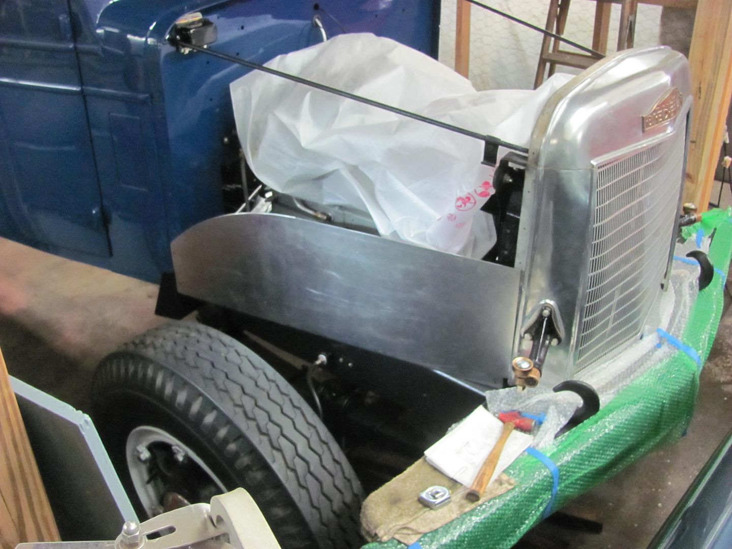
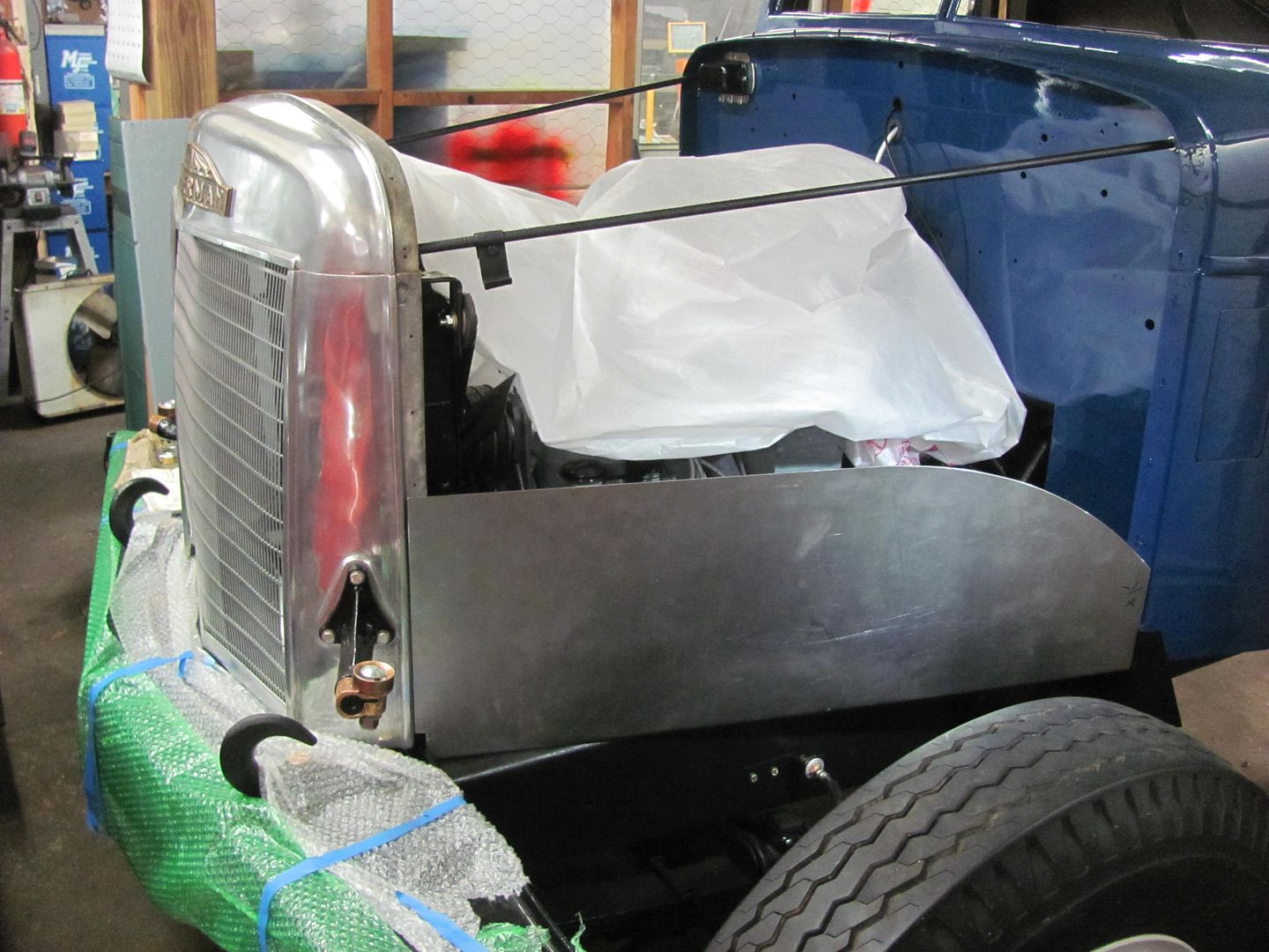
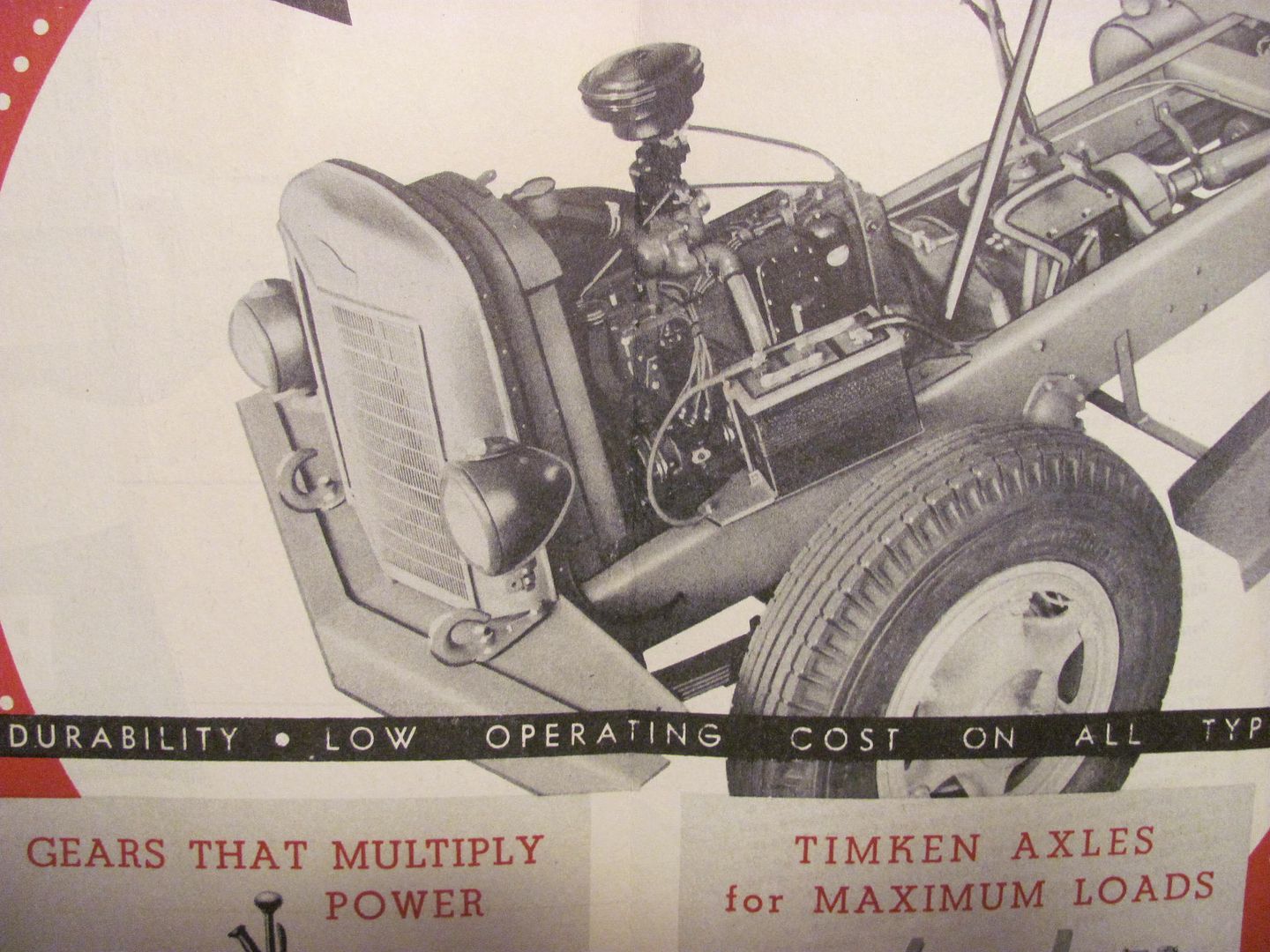
    Tonight in the shop we started the repair work on the front fenders for the 1947 Biederman Truck, seen here for reference:


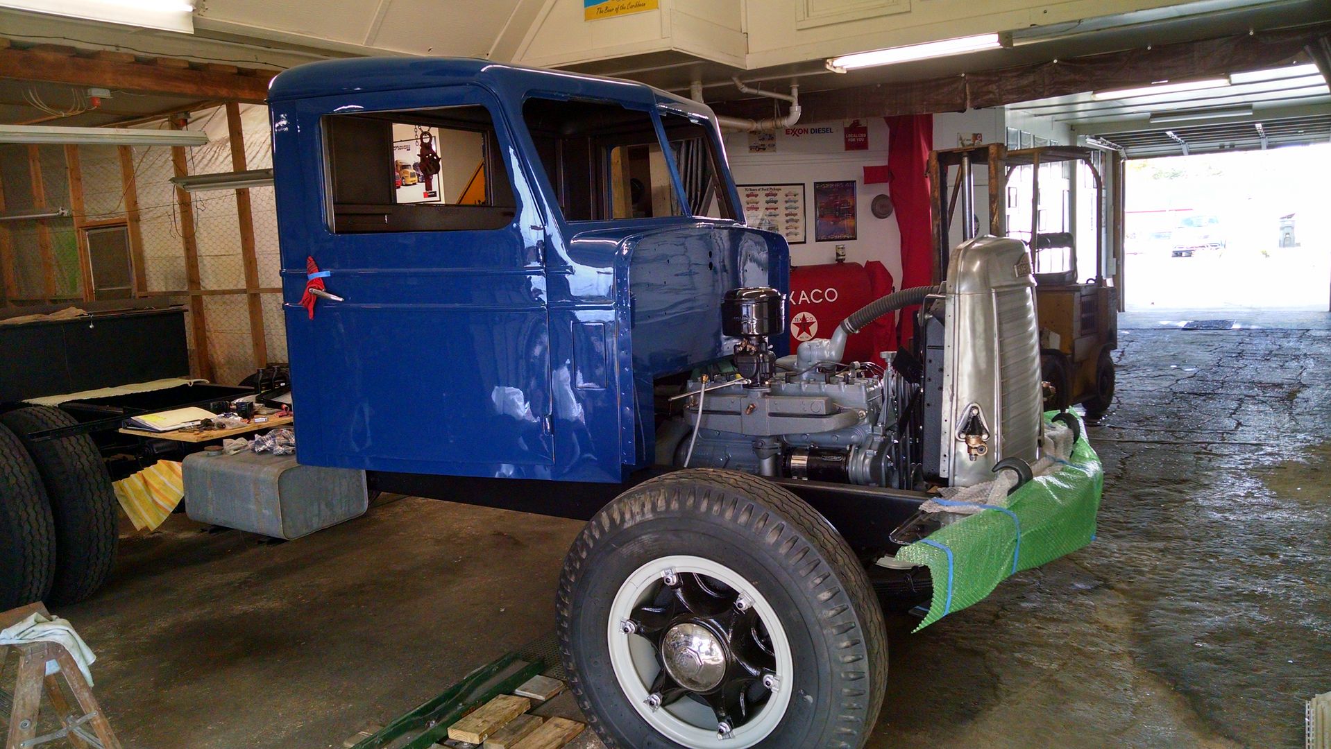
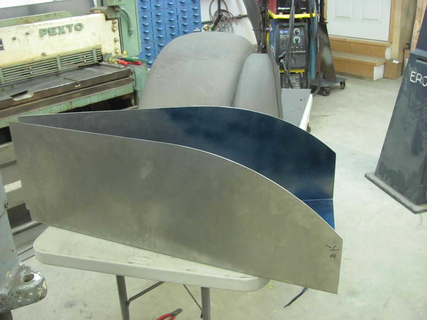
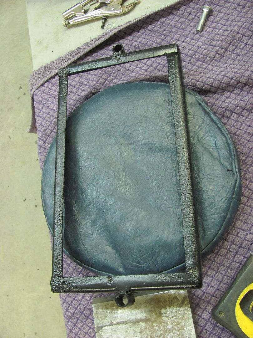
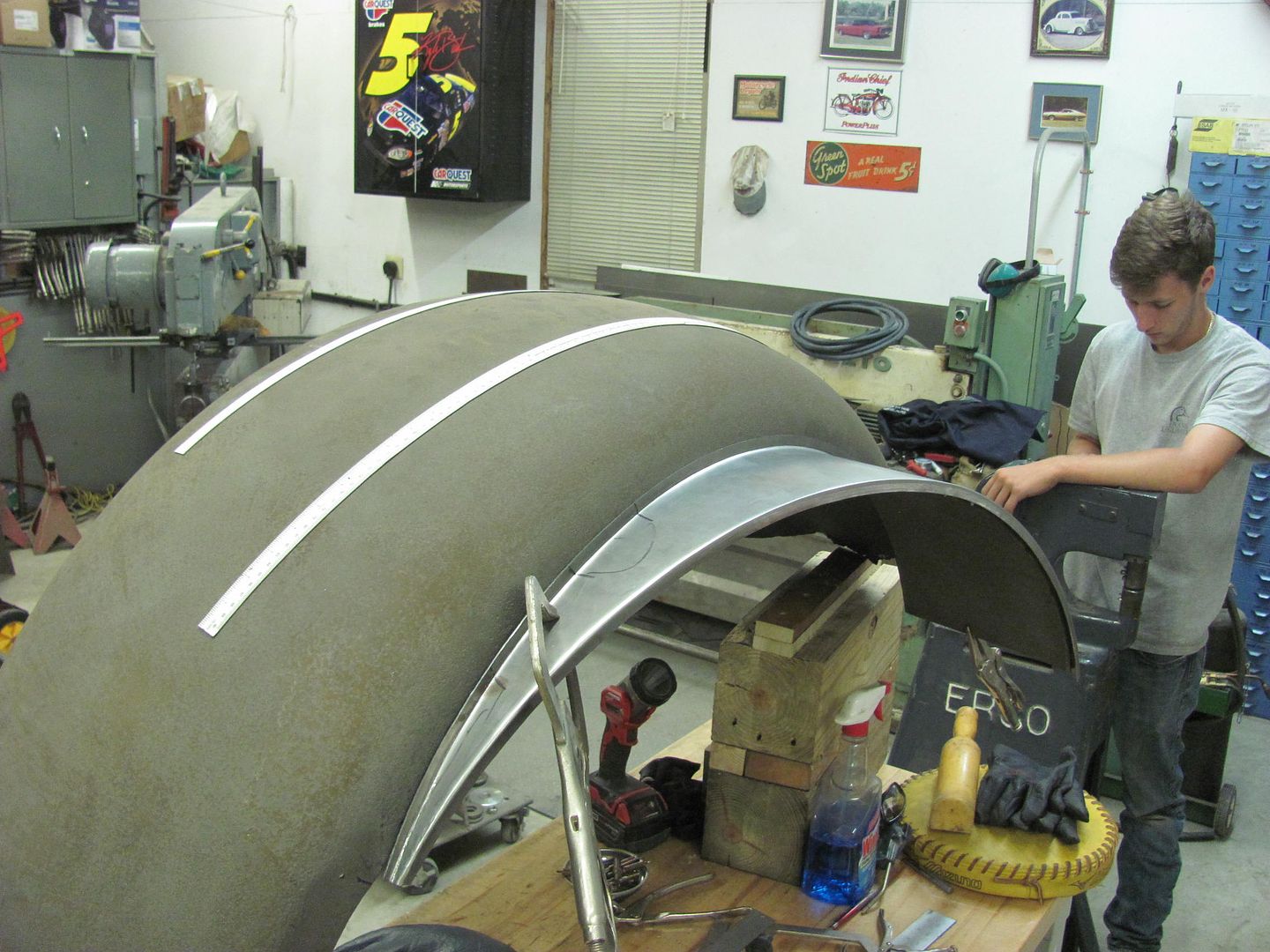
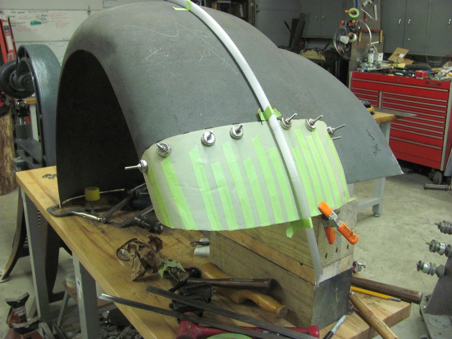
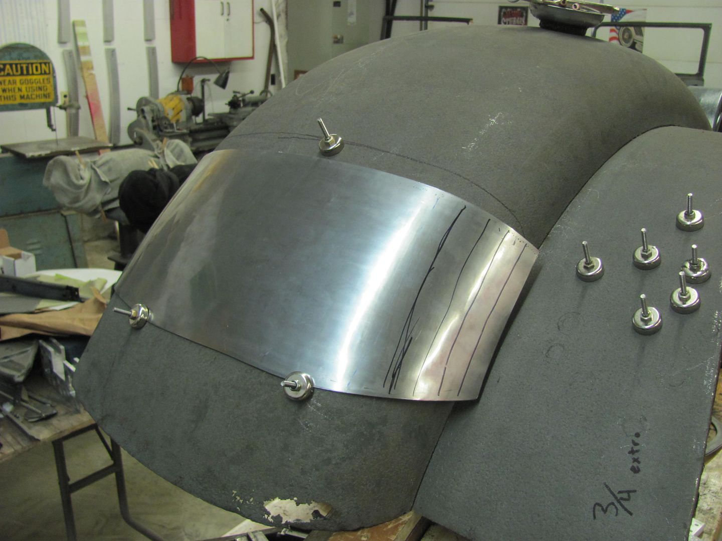
    The fenders are made using 16 gauge steel, so this may be a bit challenging when we get to blocking and wheeling patches for the fenders themselves. In the meantime (while still waiting for the new English wheel) let's get started on the inner fenders. The driver's side is the worst, with so much rotted away that we couldn't get accurate dimensions. The passenger side was in much better condition, but just shy of 70 years has taken its toll in adding some wavy distortion. So we'll remake both sides for a better match.


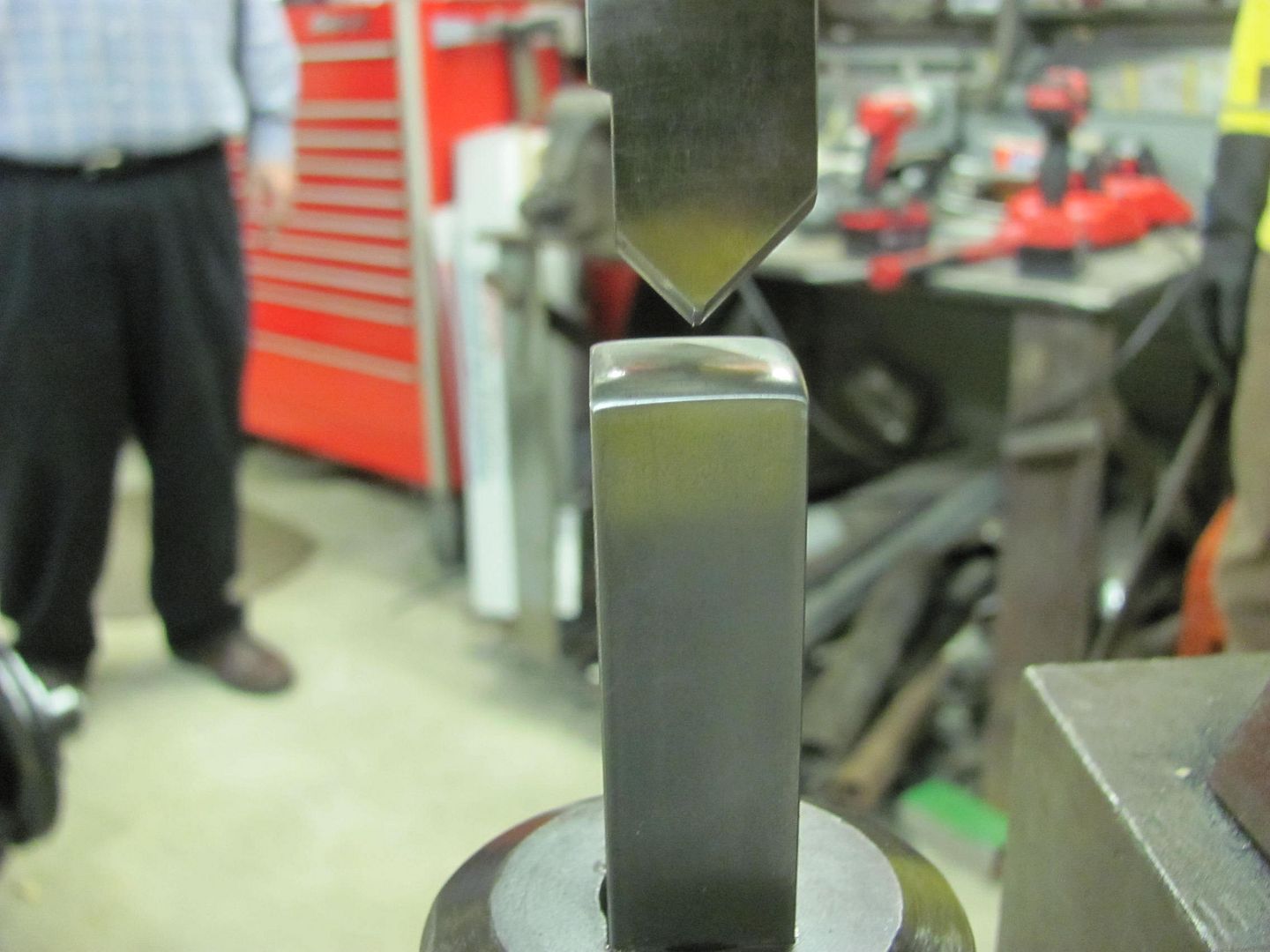
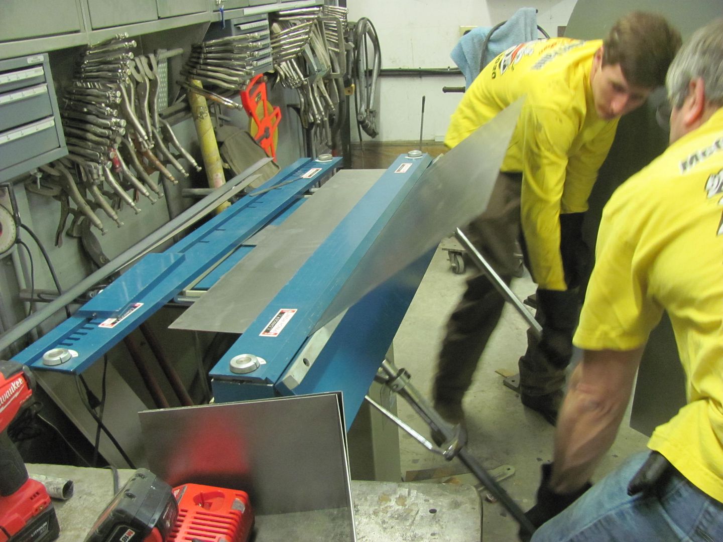
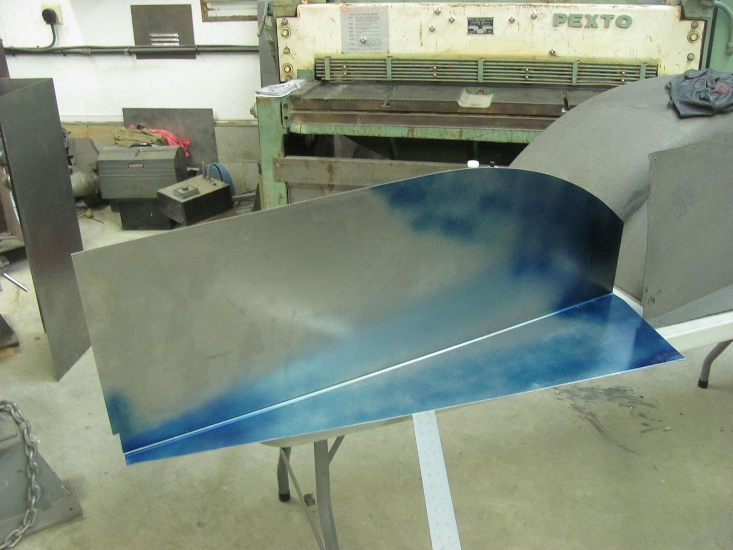
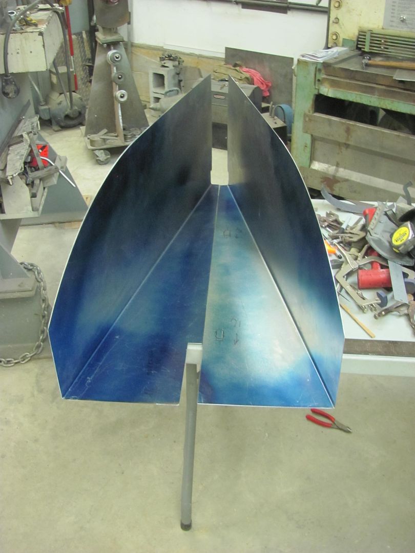
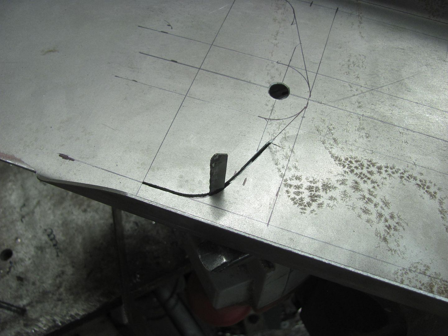
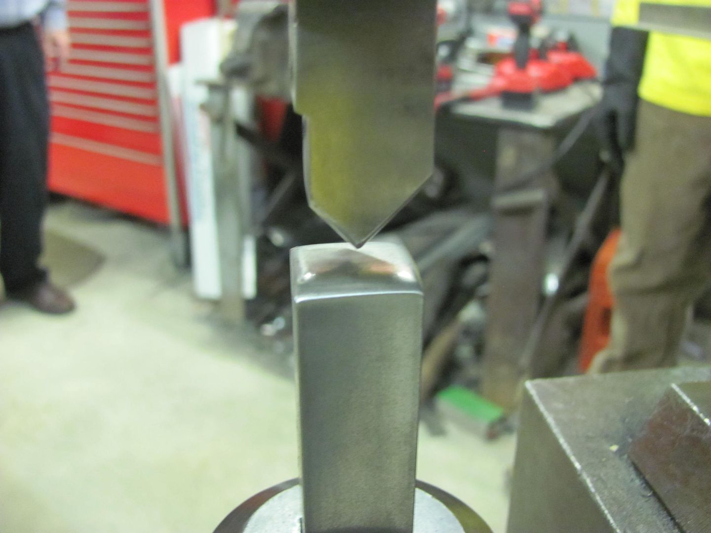
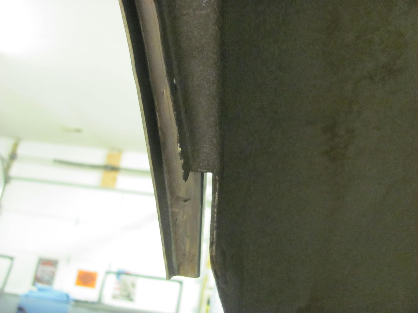
    In order to get a more crisp bend on the 16 gauge steel, we used a tipping die in the Lennox to thin the metal at the line of the bend.


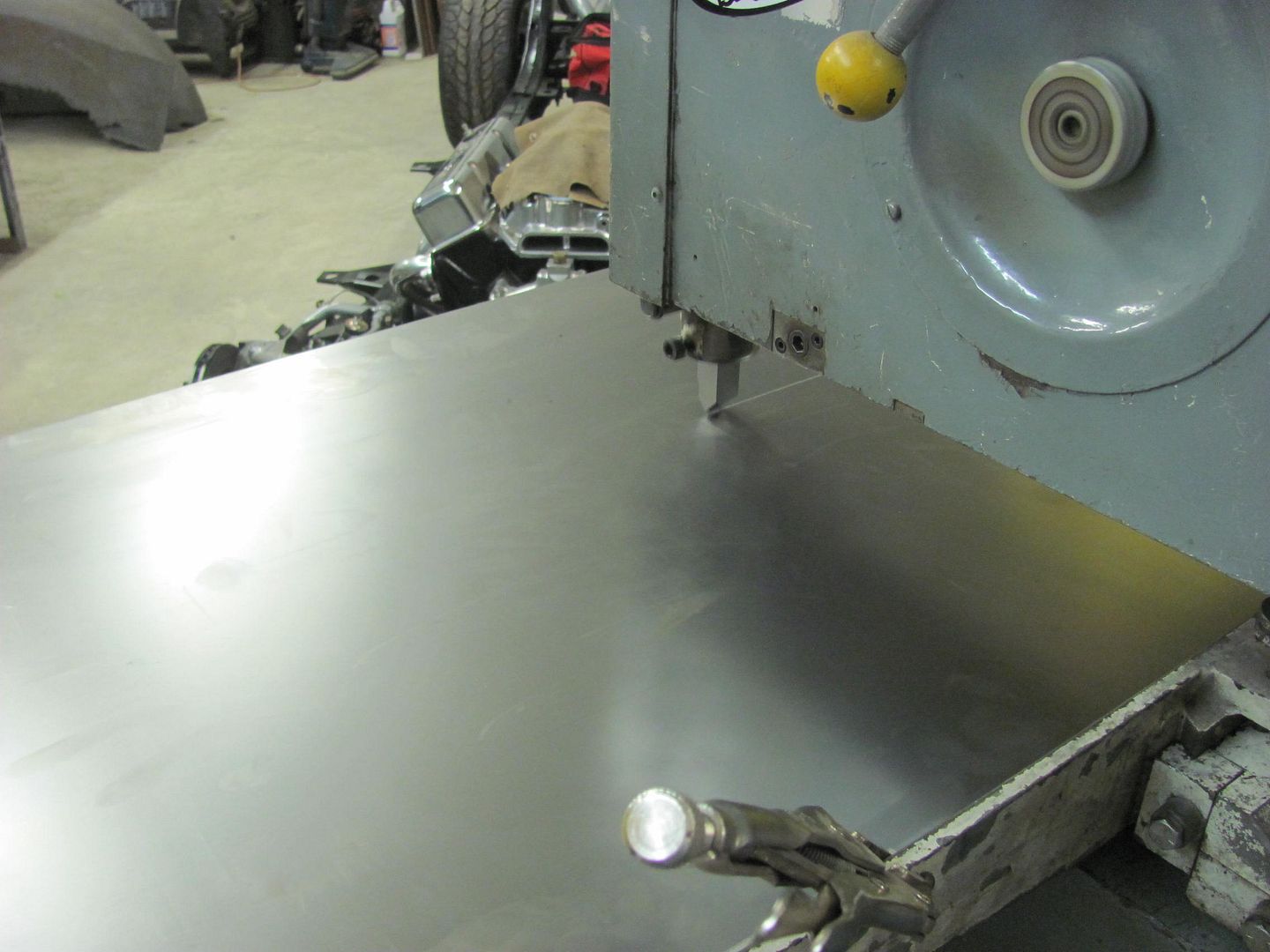
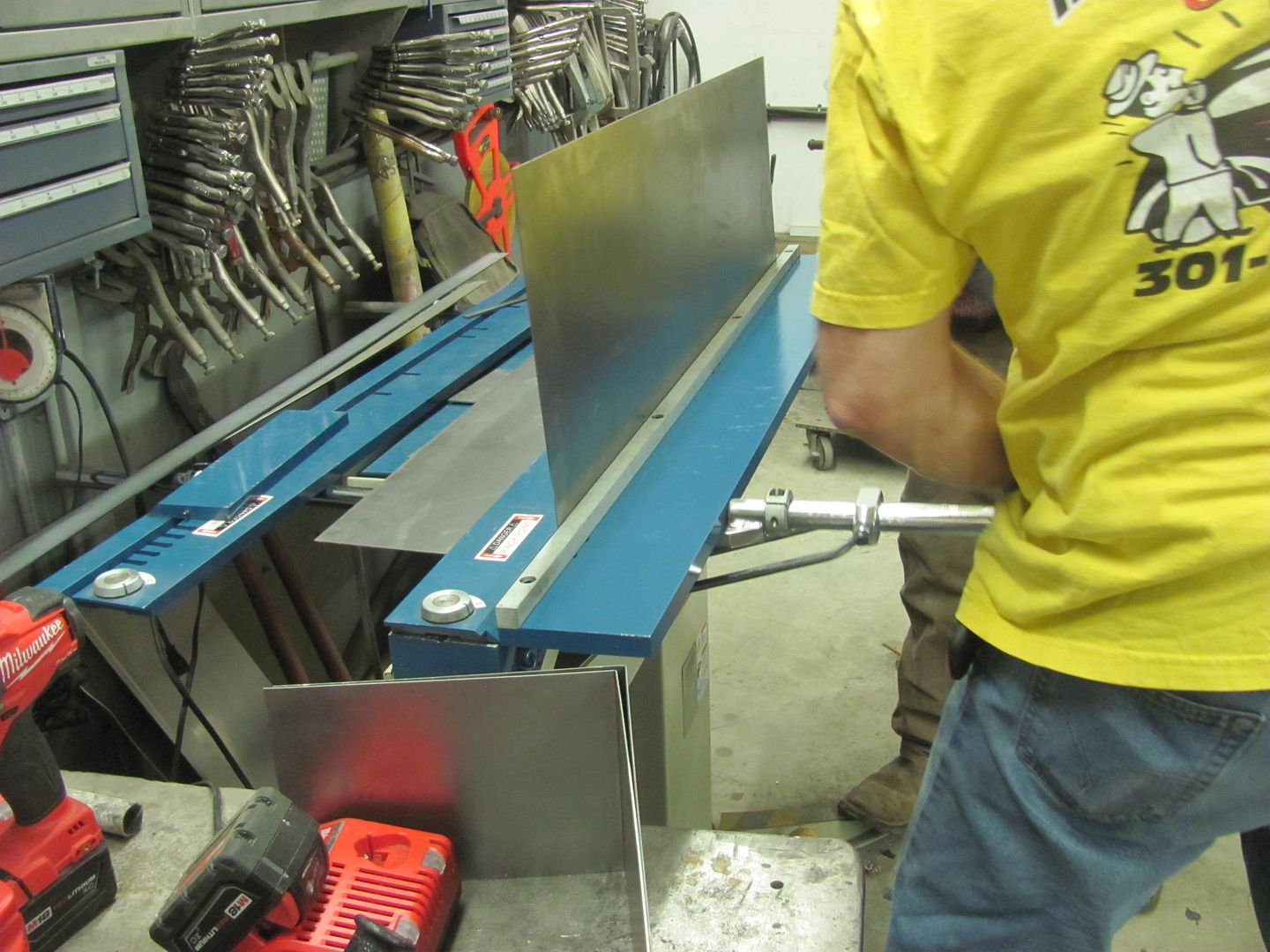
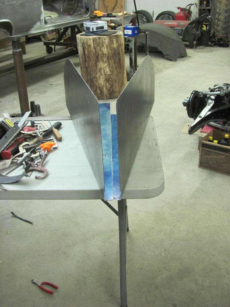
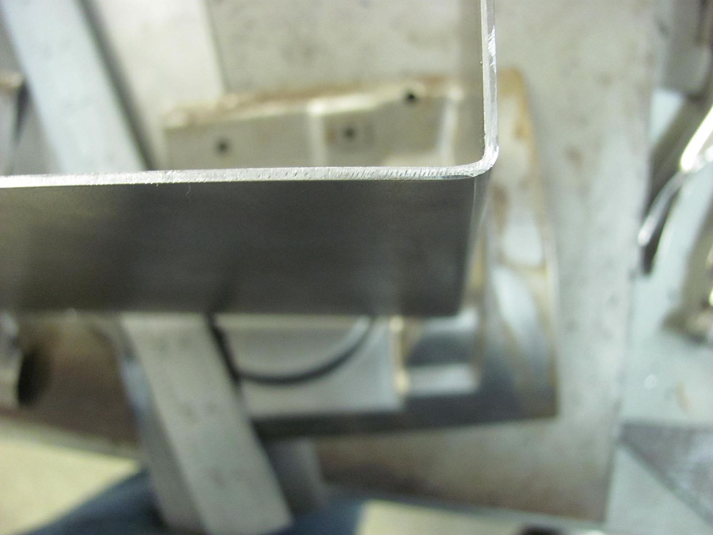
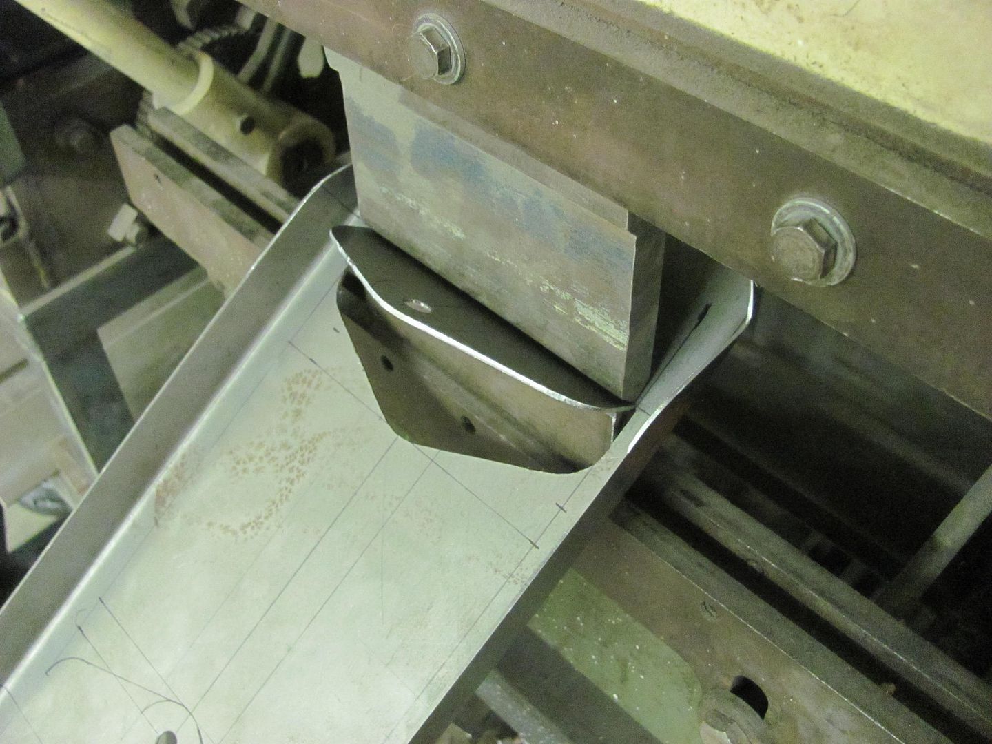
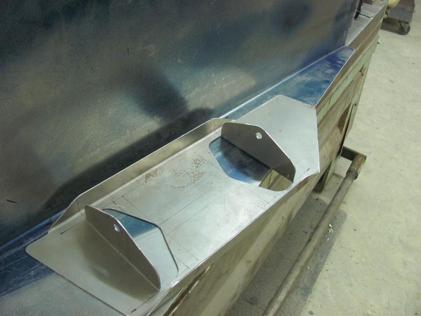
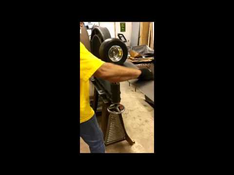
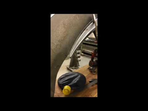
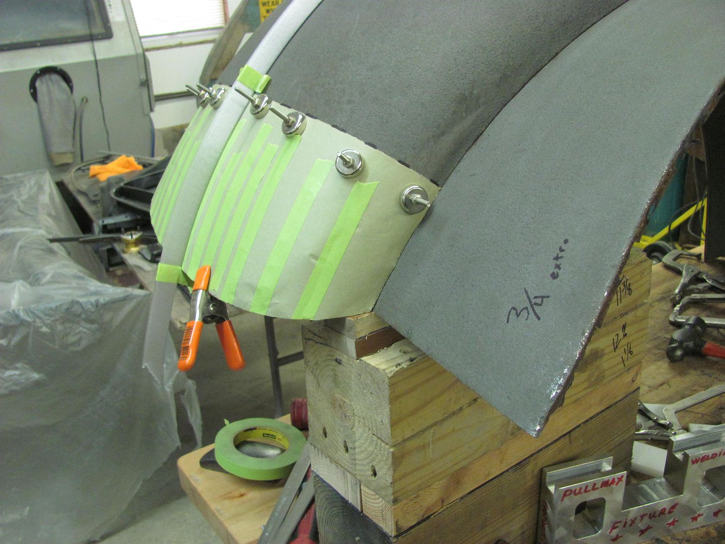
    Bending in the Baileigh Magnetic Brake..


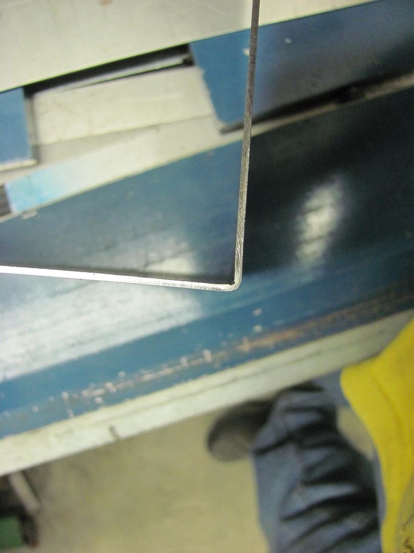
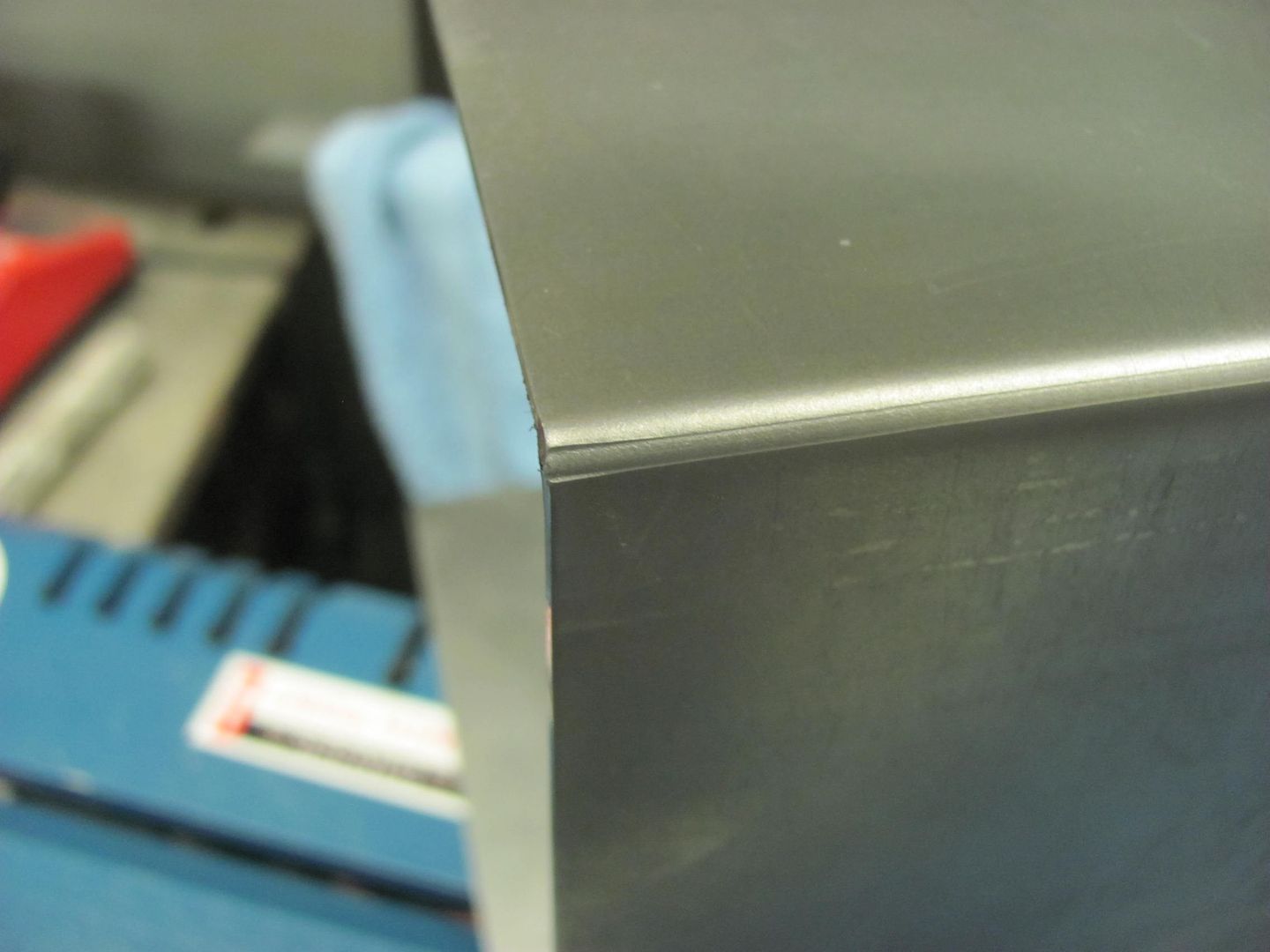
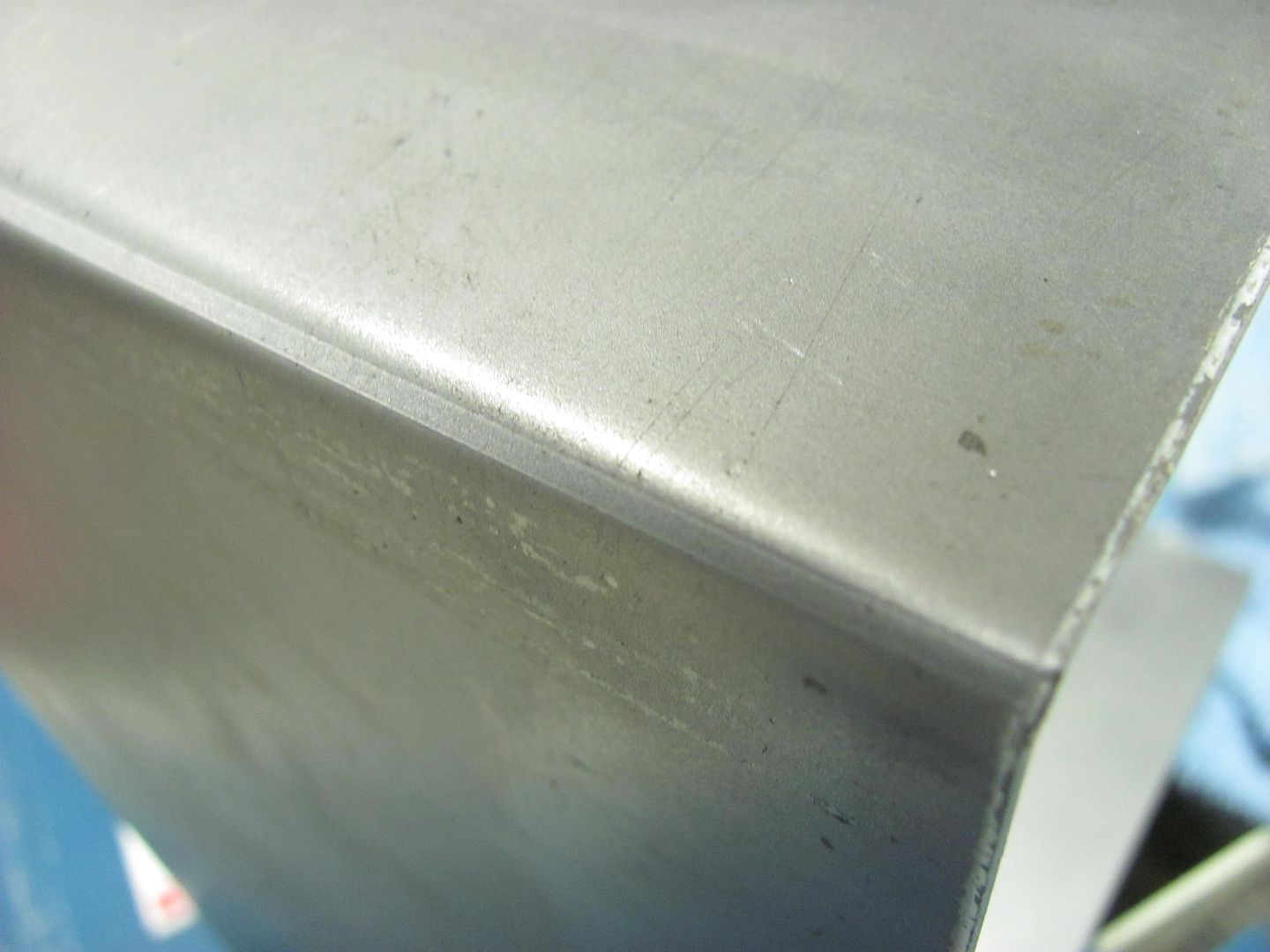
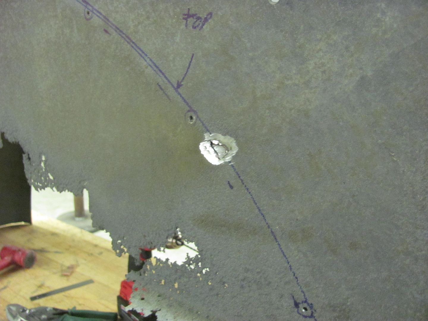
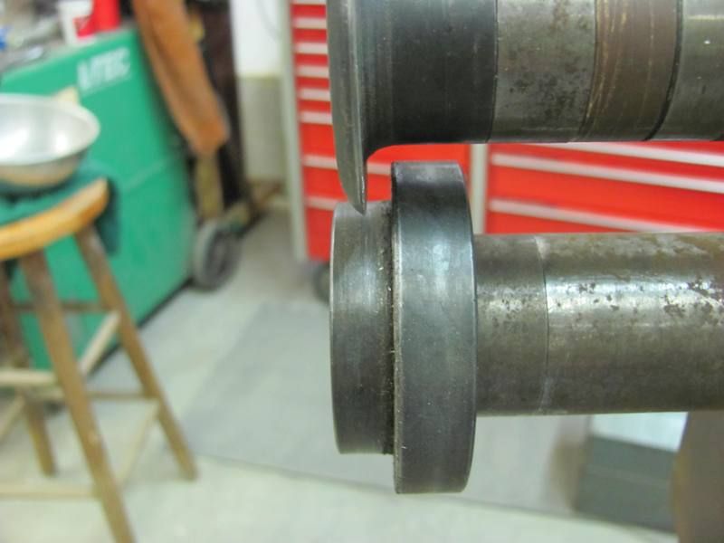
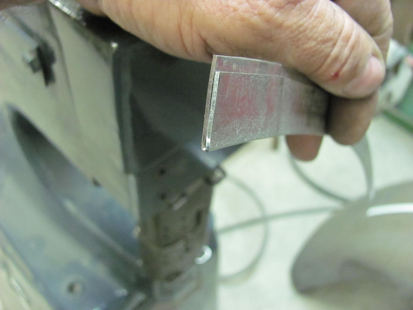
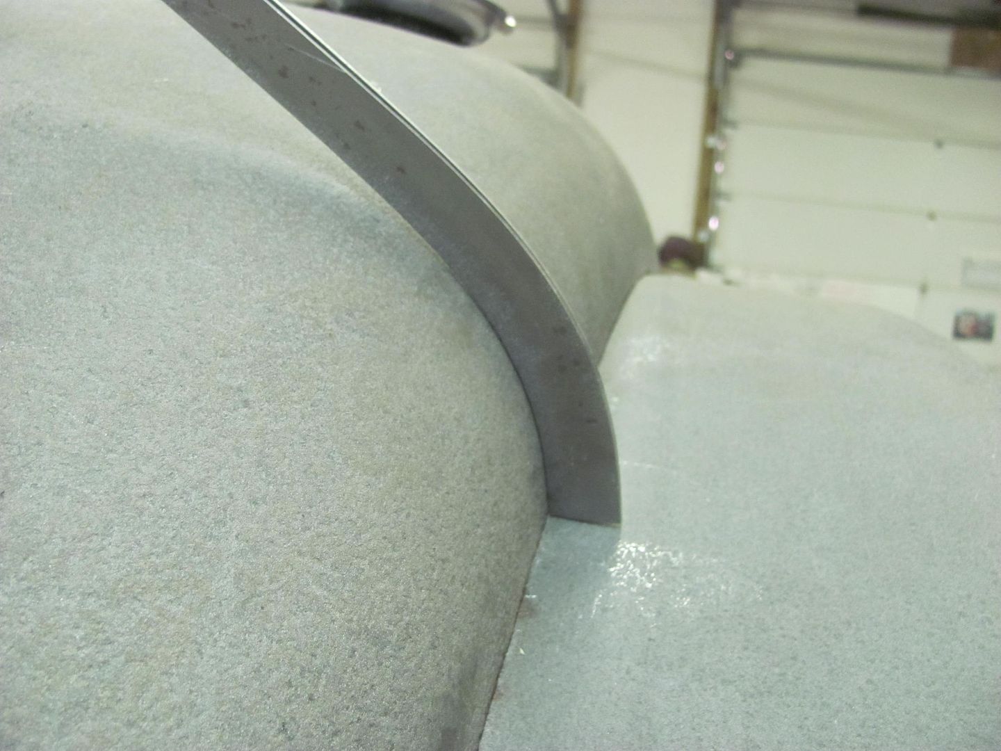
    This detail shot shows how the thinning helps get a tighter bend..


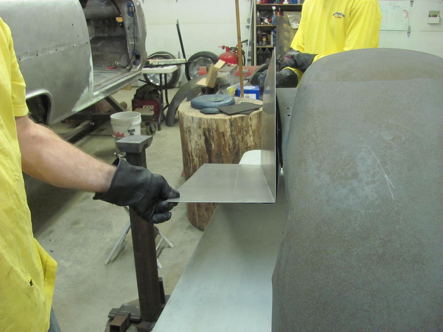
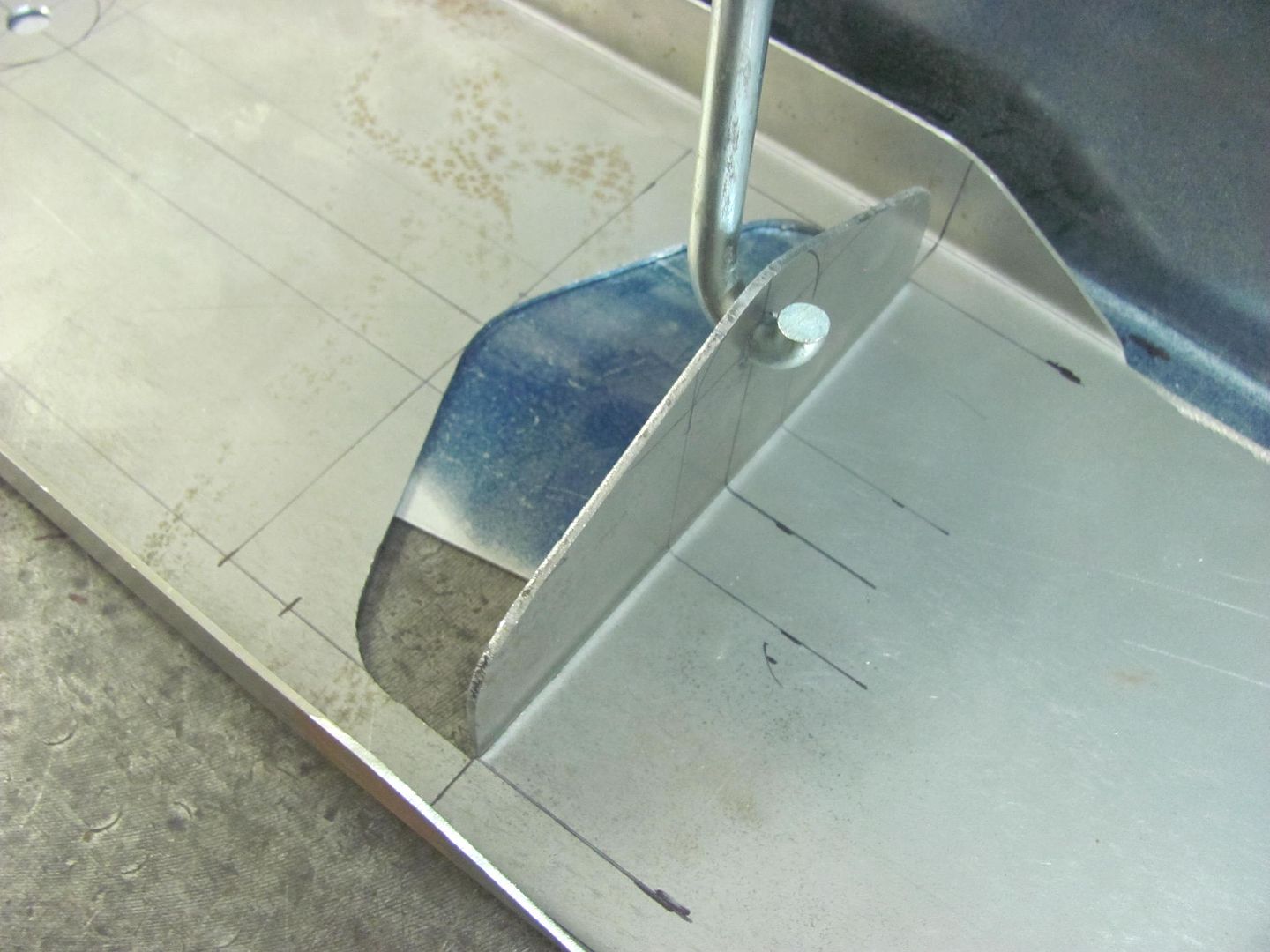
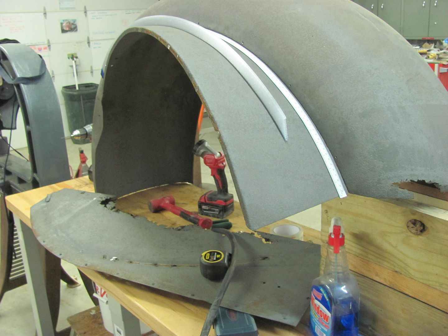
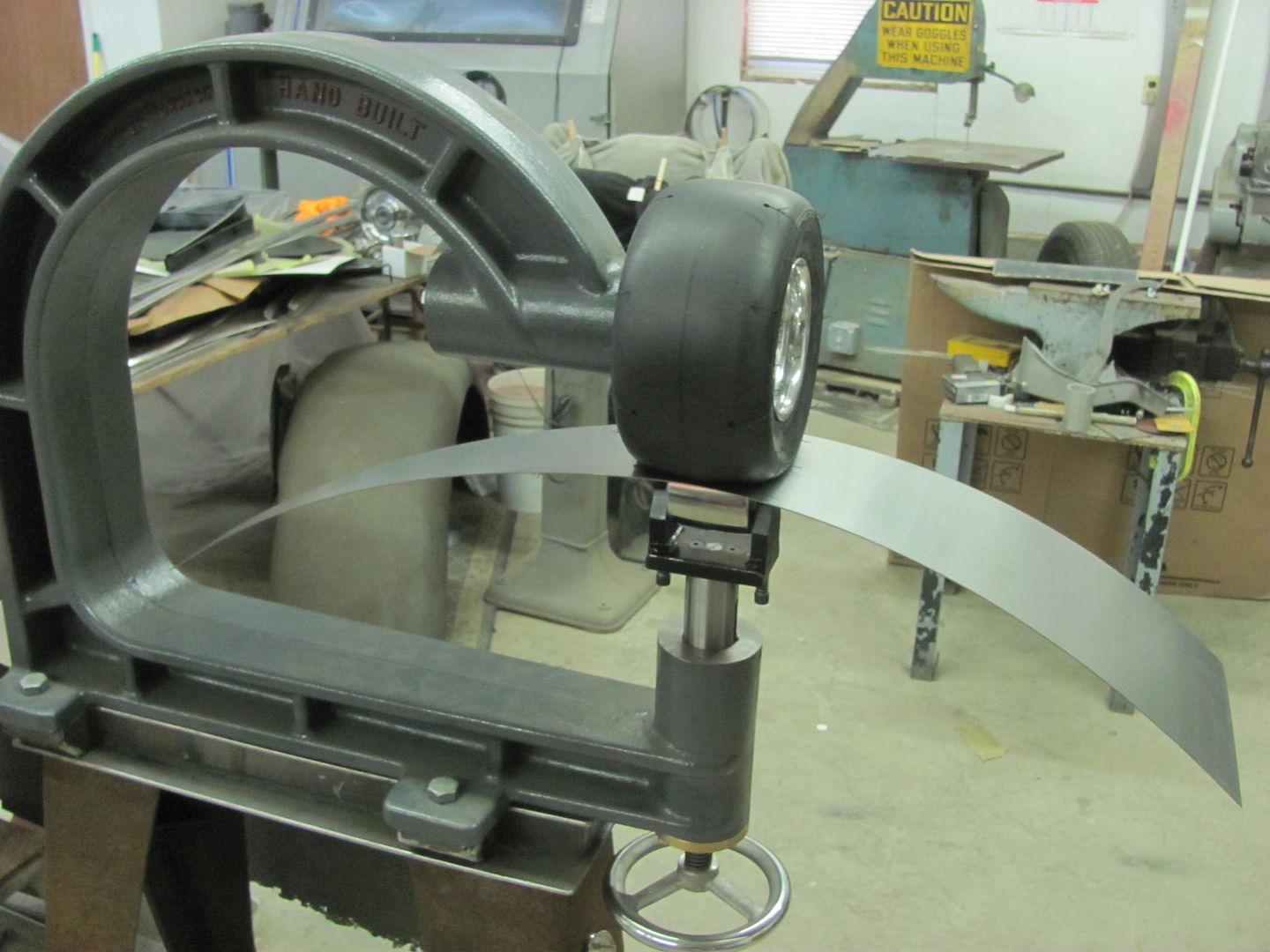
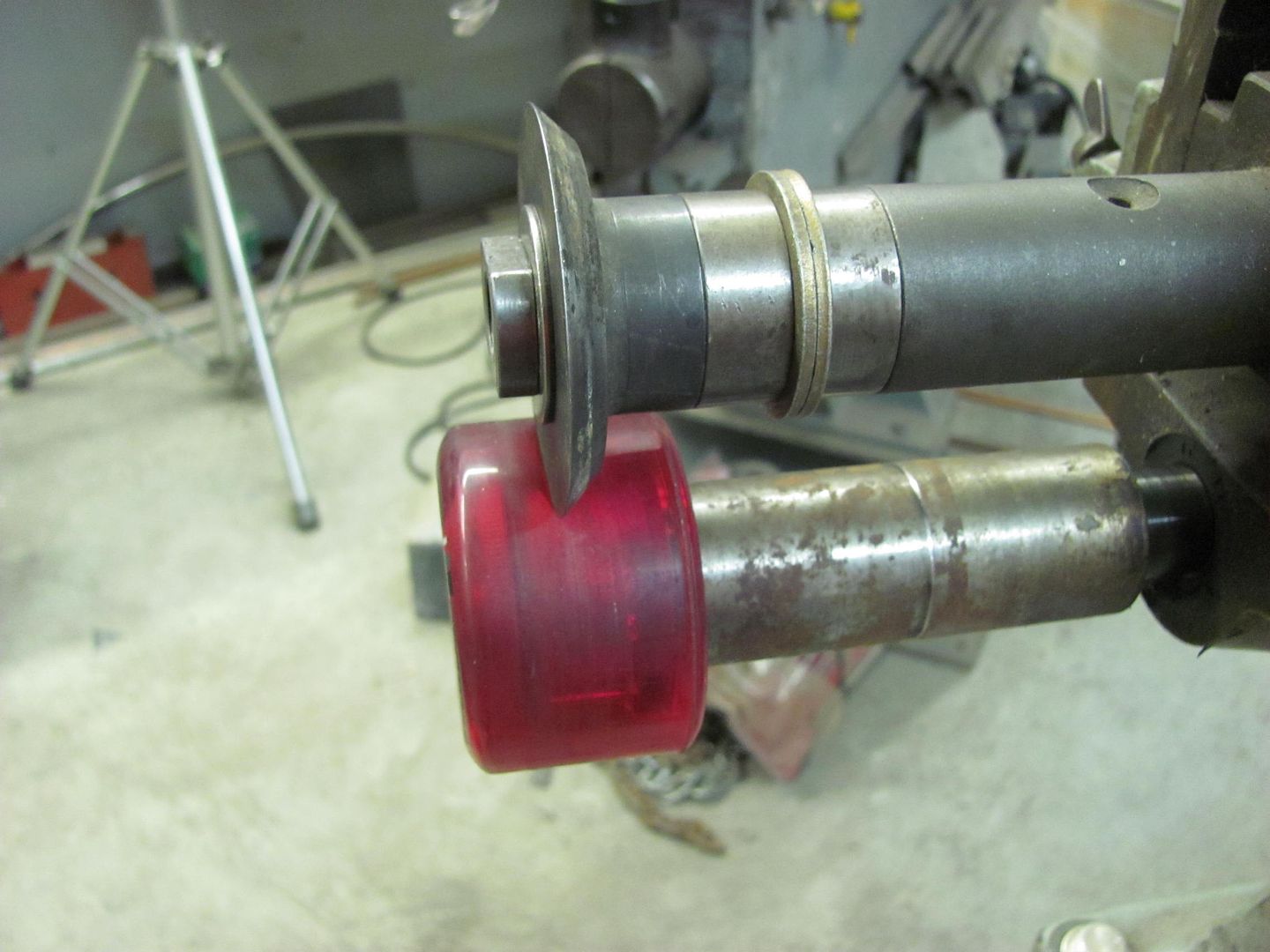
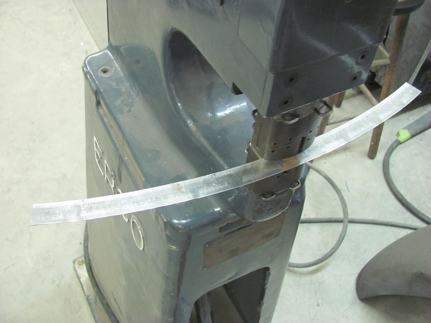
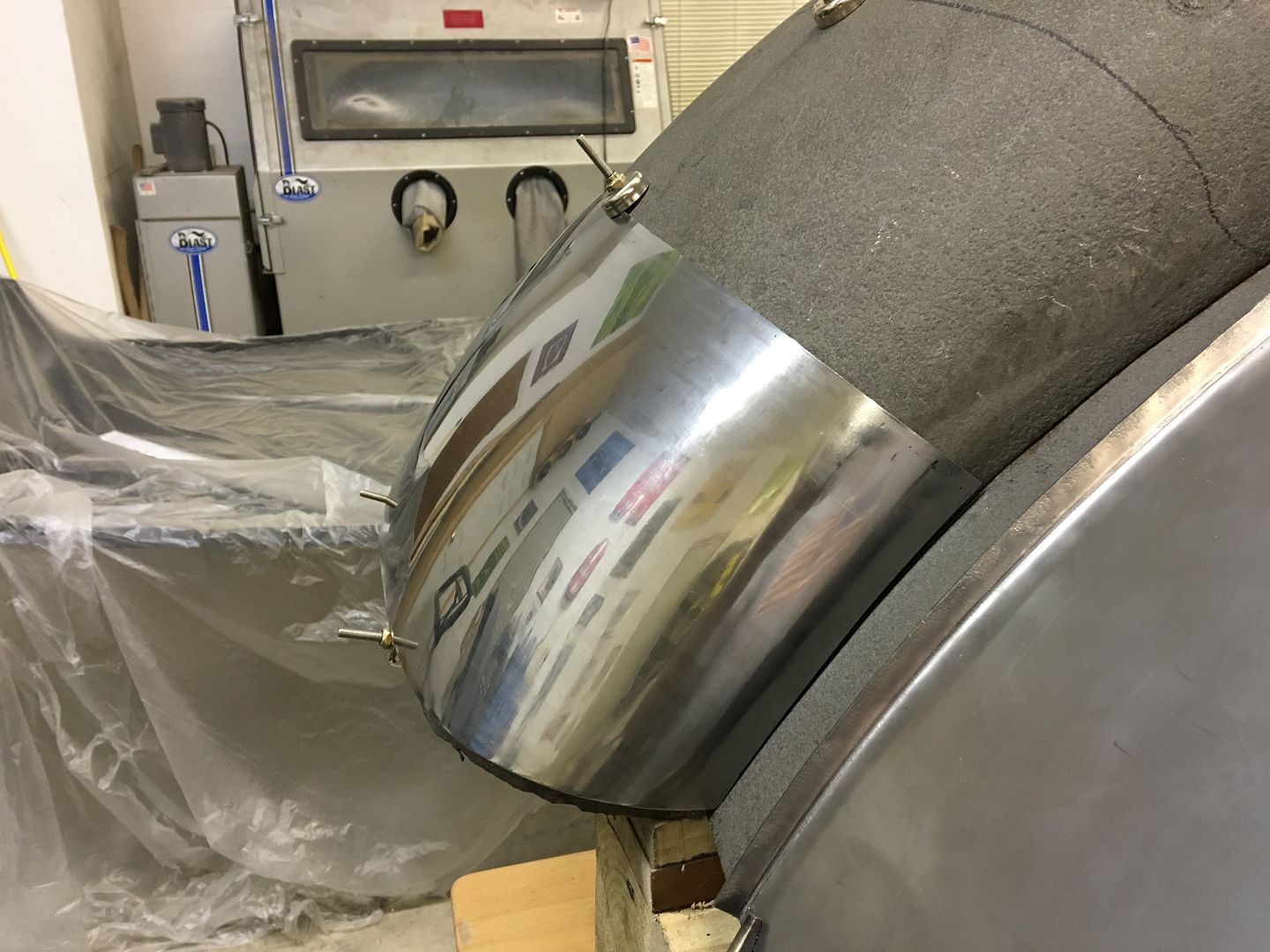
    Next, we needed a profile template for the rear radius, so the kick shrinker is used on a folded 19 gauge strip to add the radius..


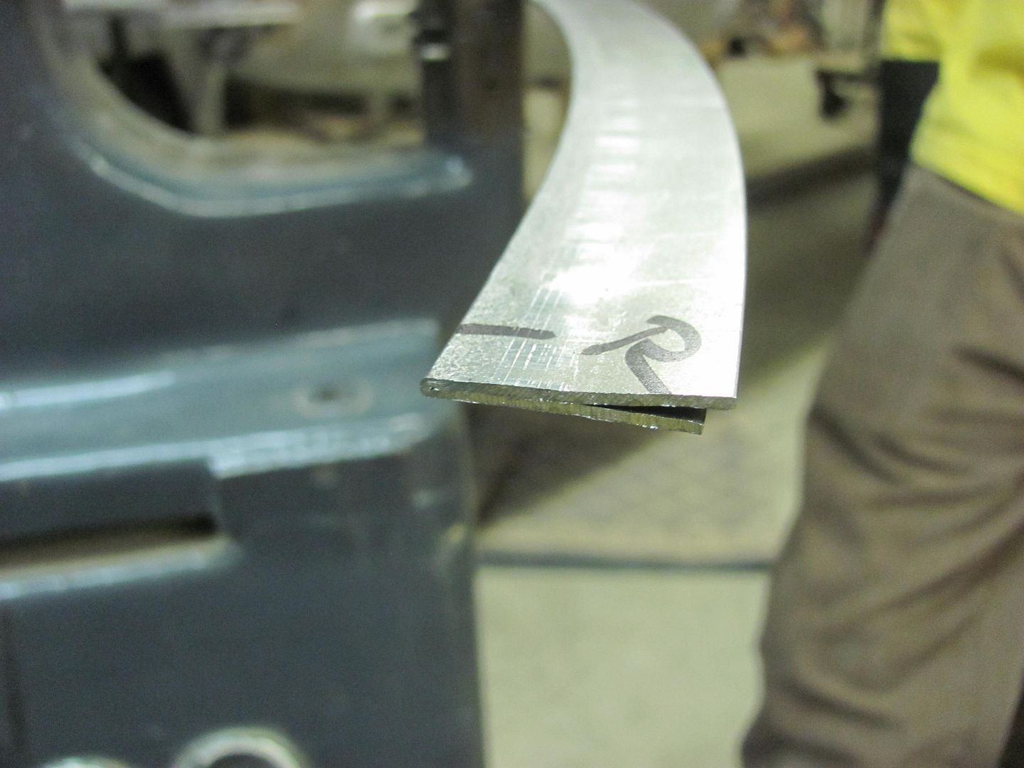
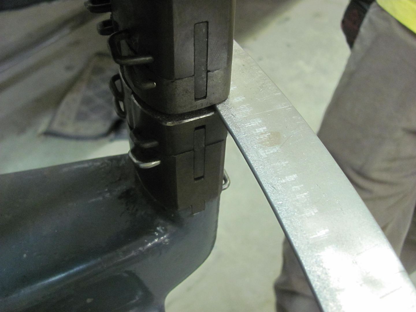
    A flat folded strip works better than an angle as if you shrink too far in this direction.....


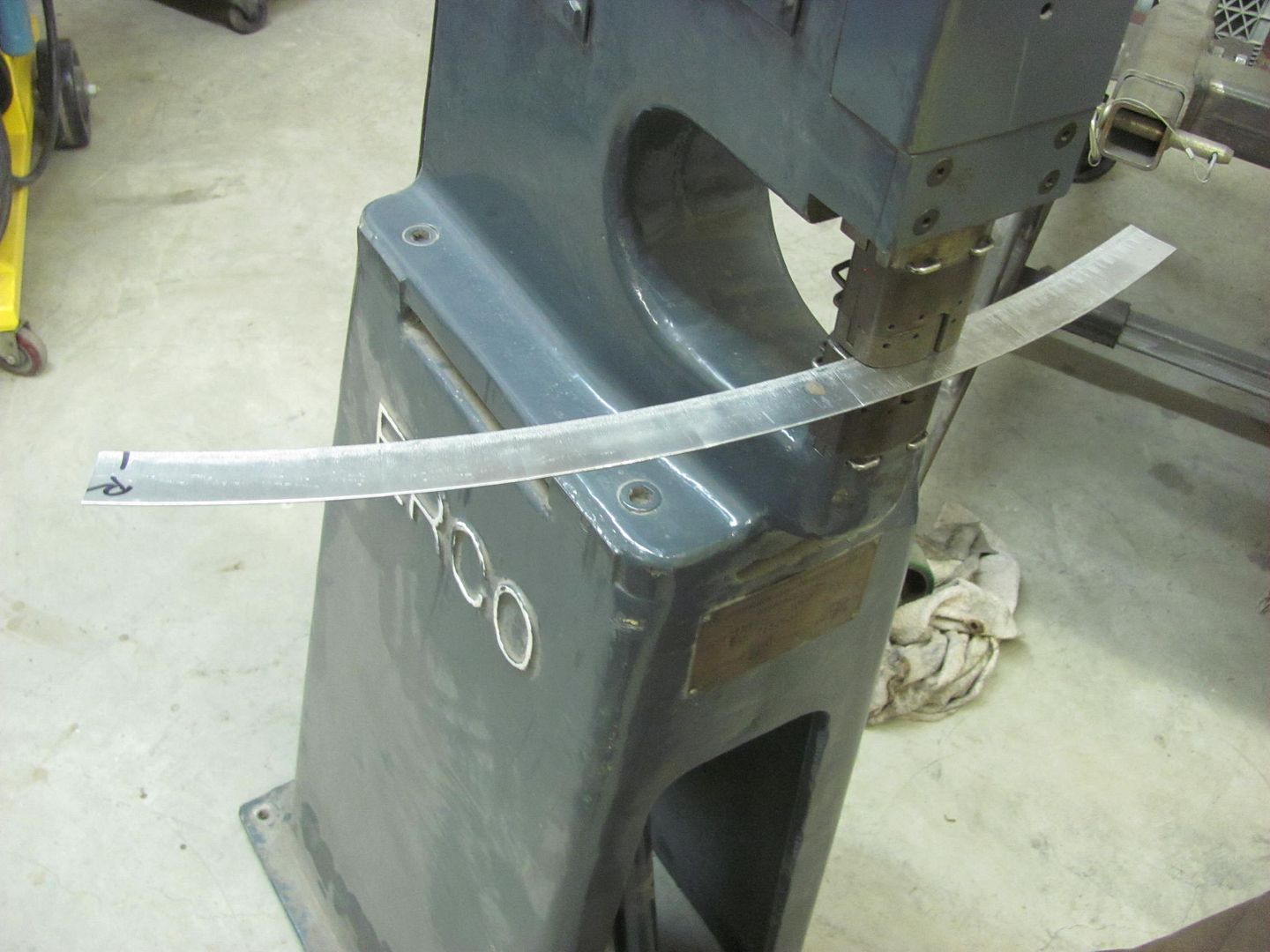
    ......you can simply shrink the back half to reverse the effect without the need for changing to the stretching die..


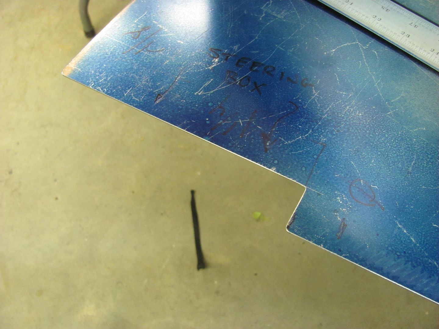
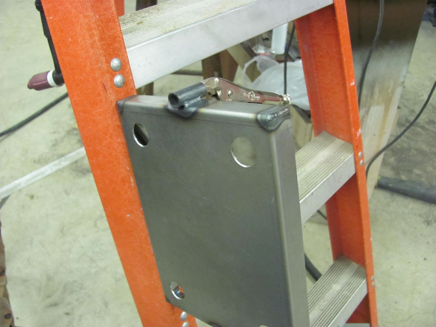
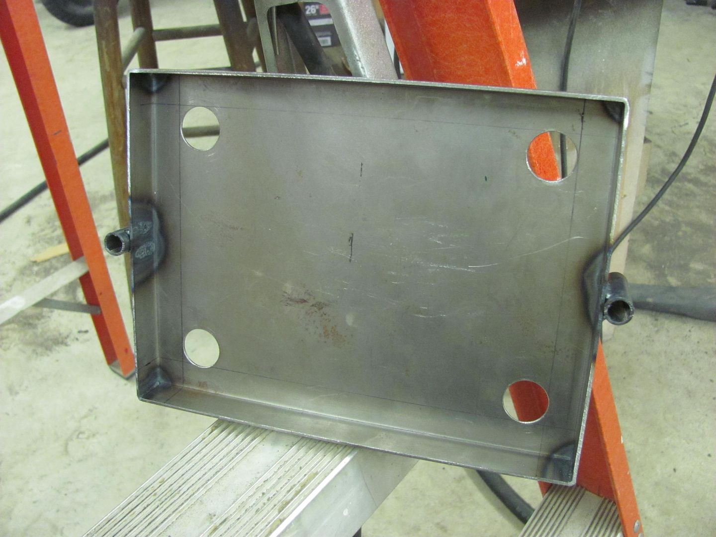
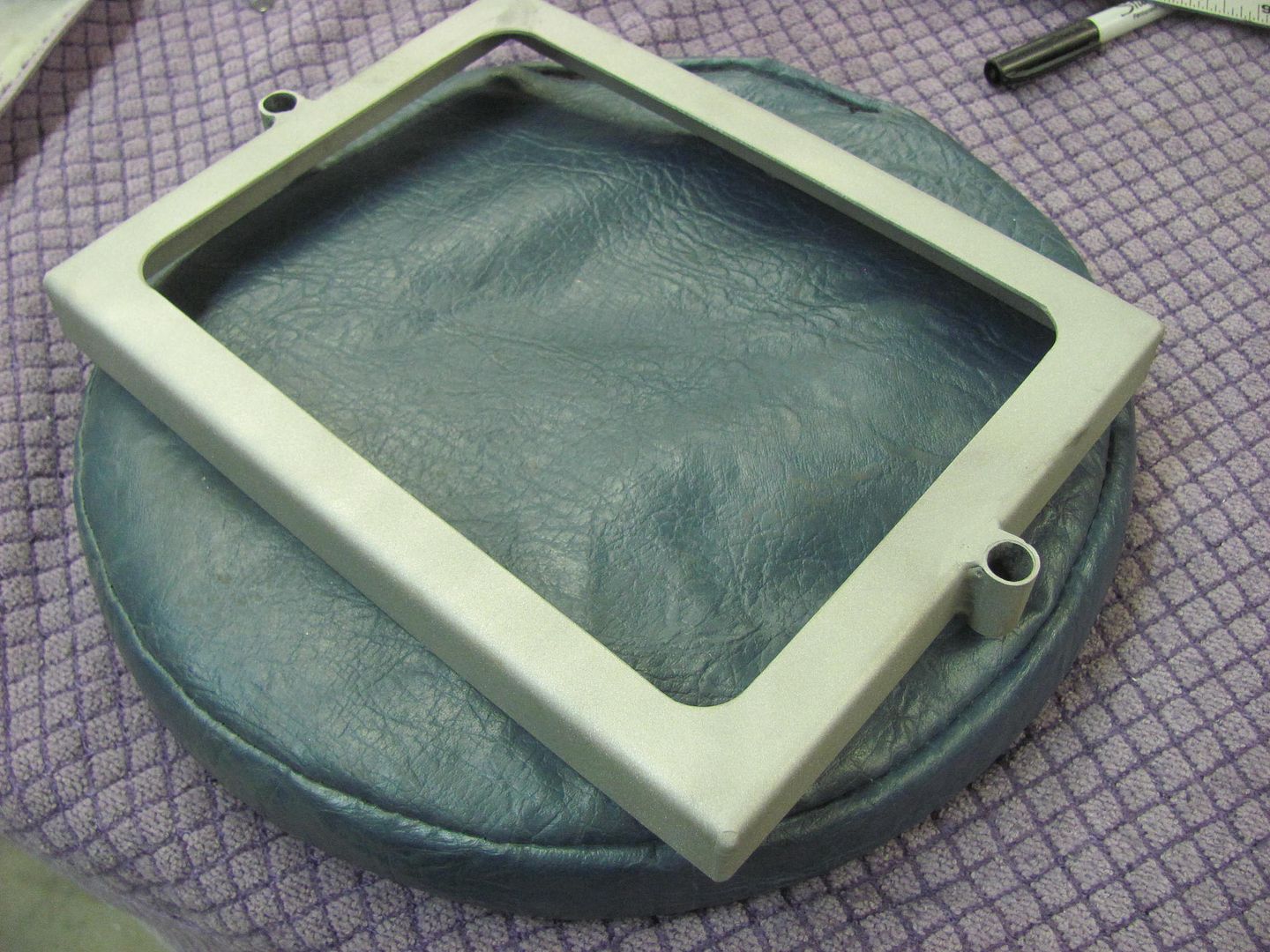
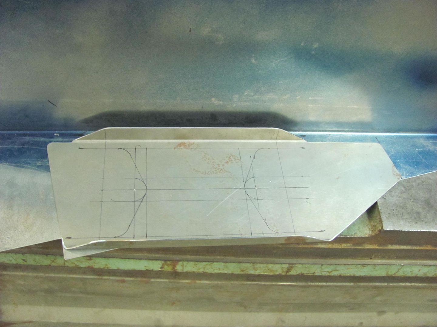
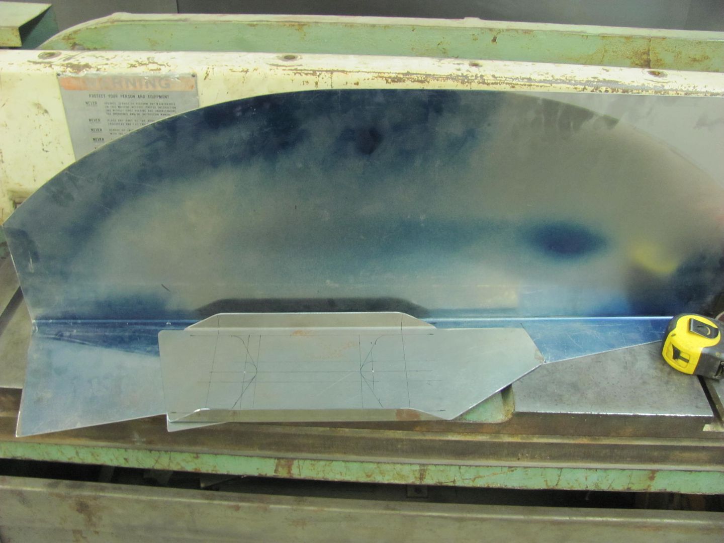
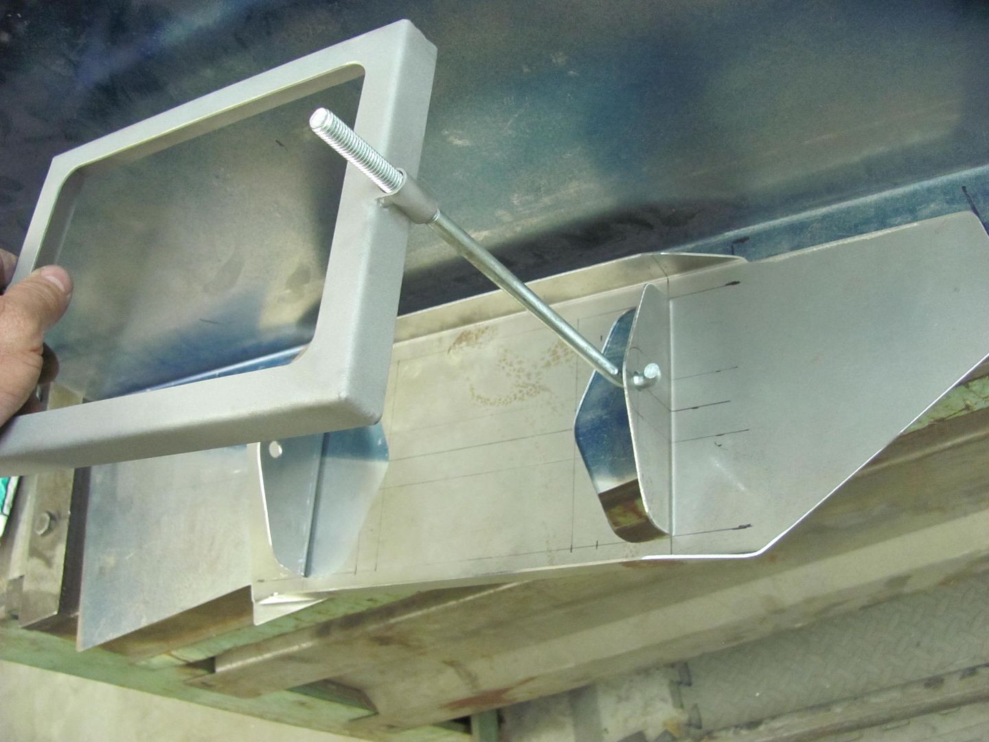
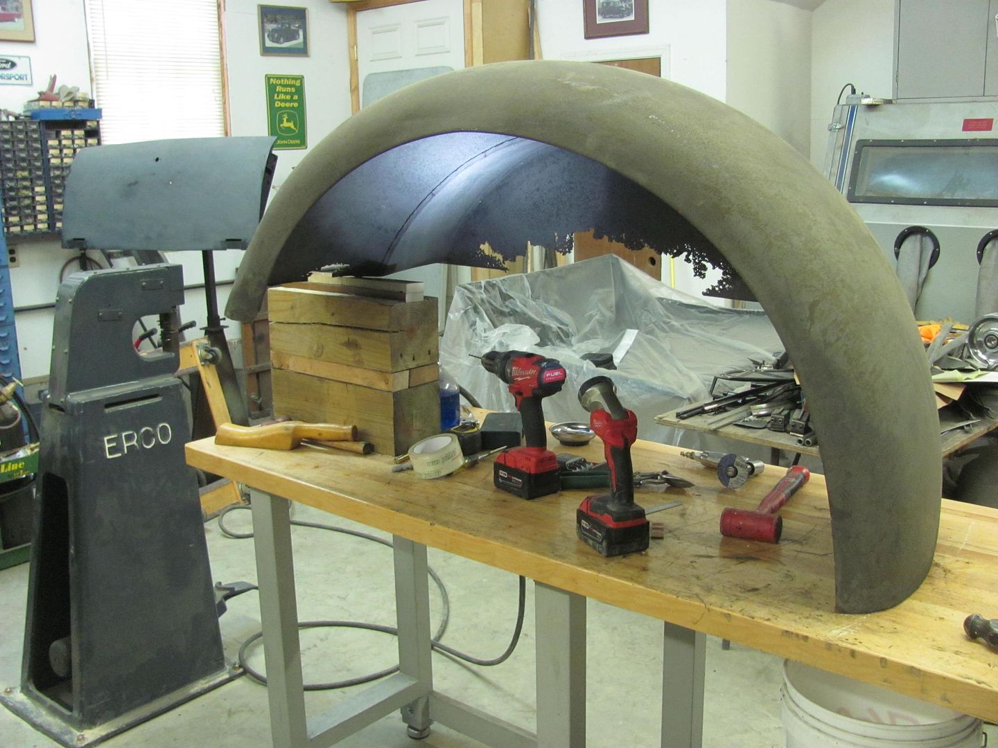
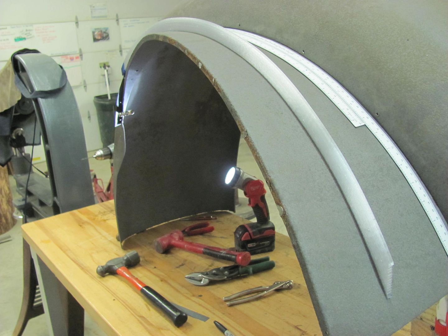
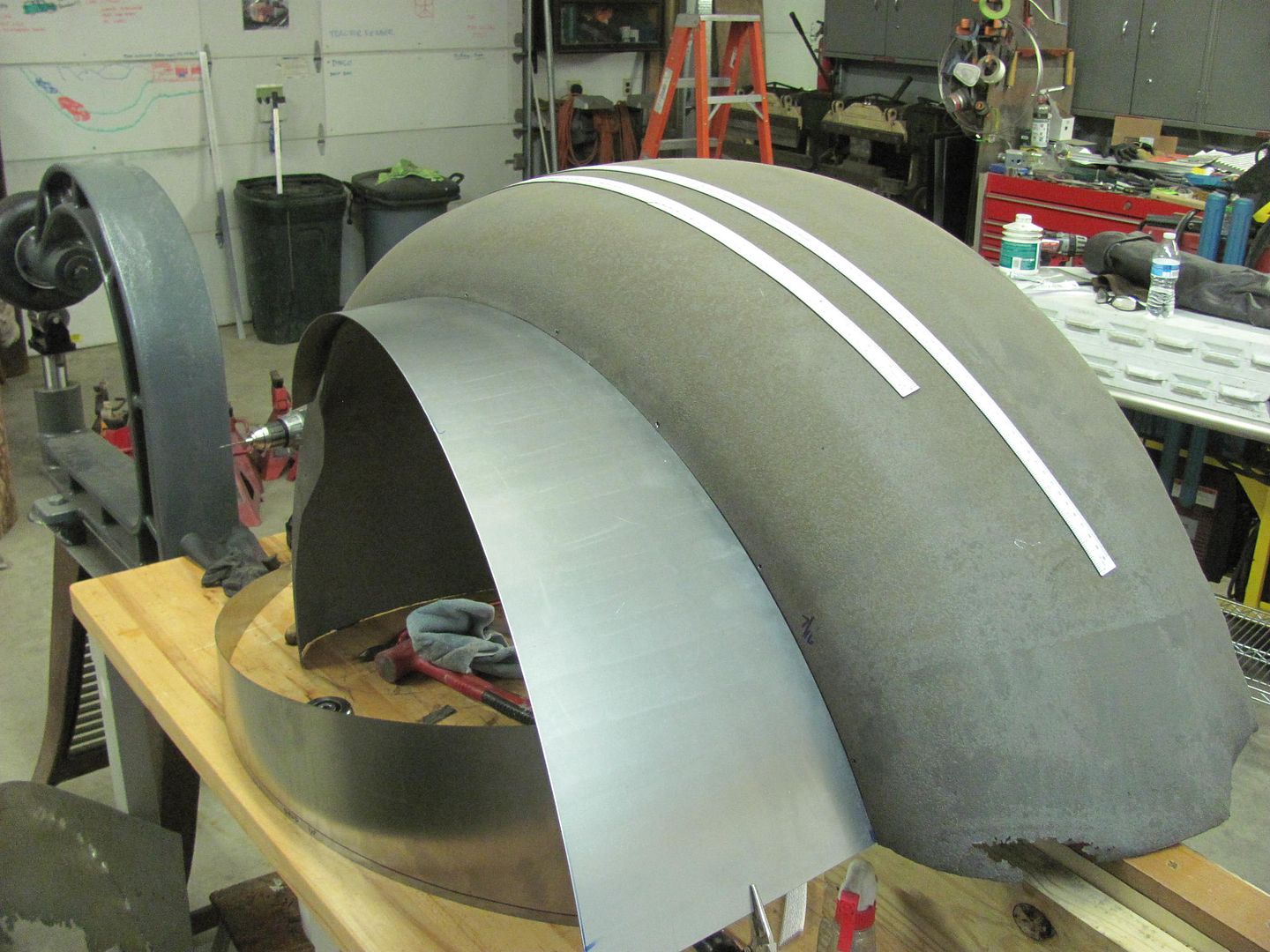
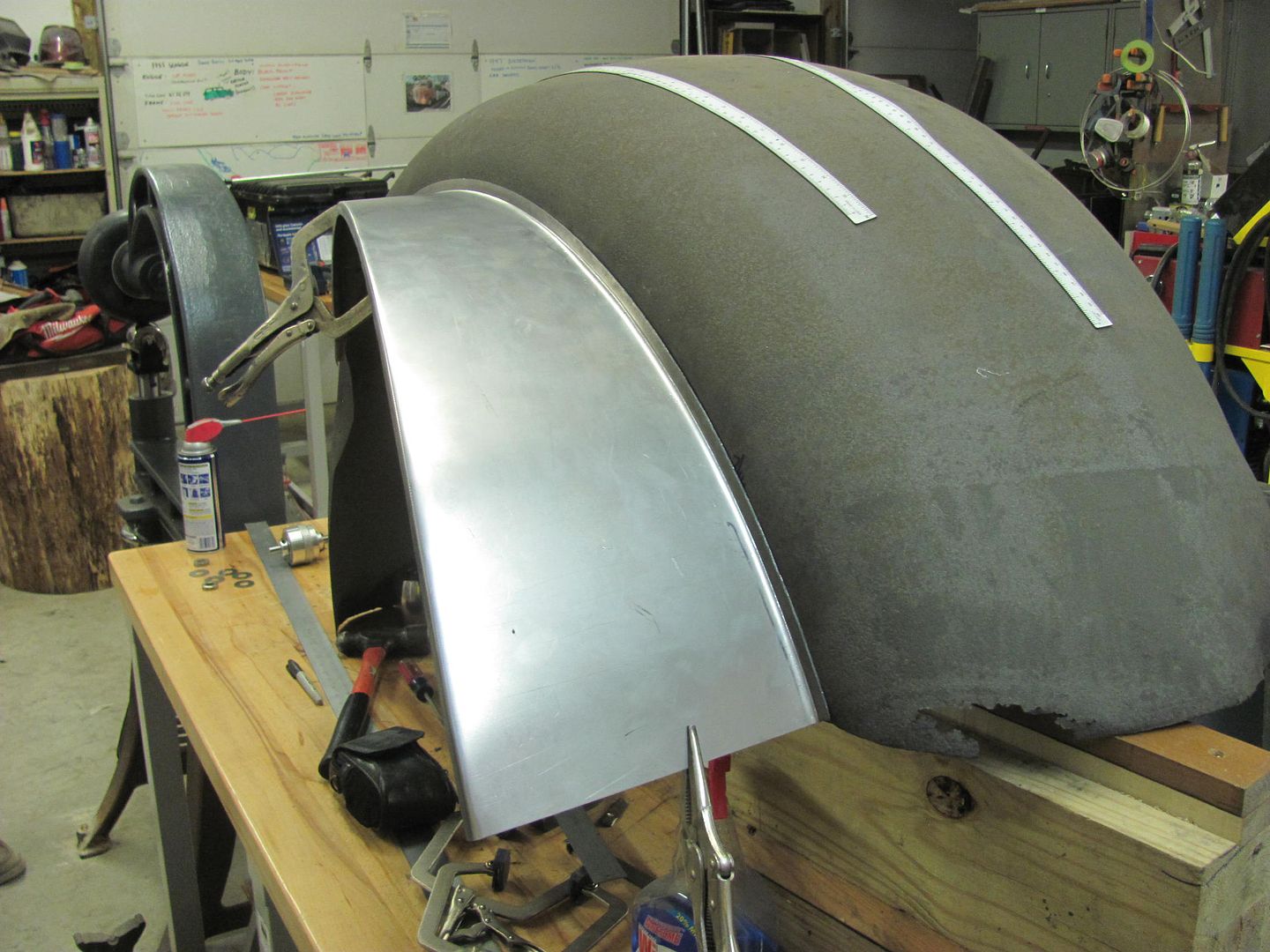
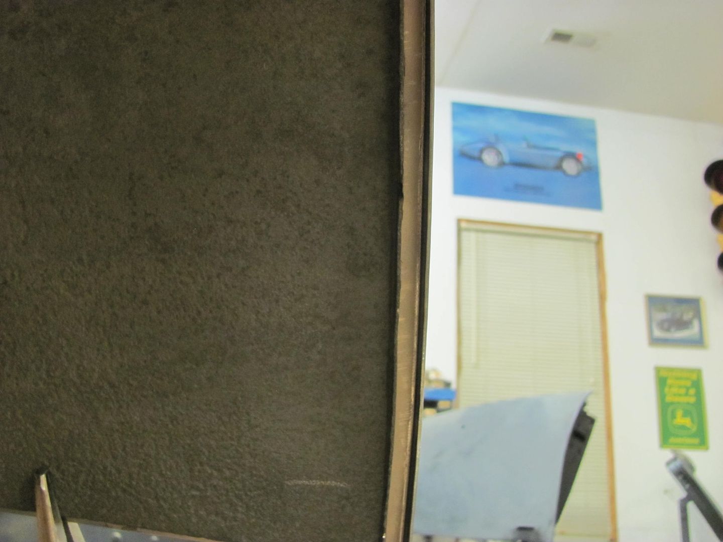
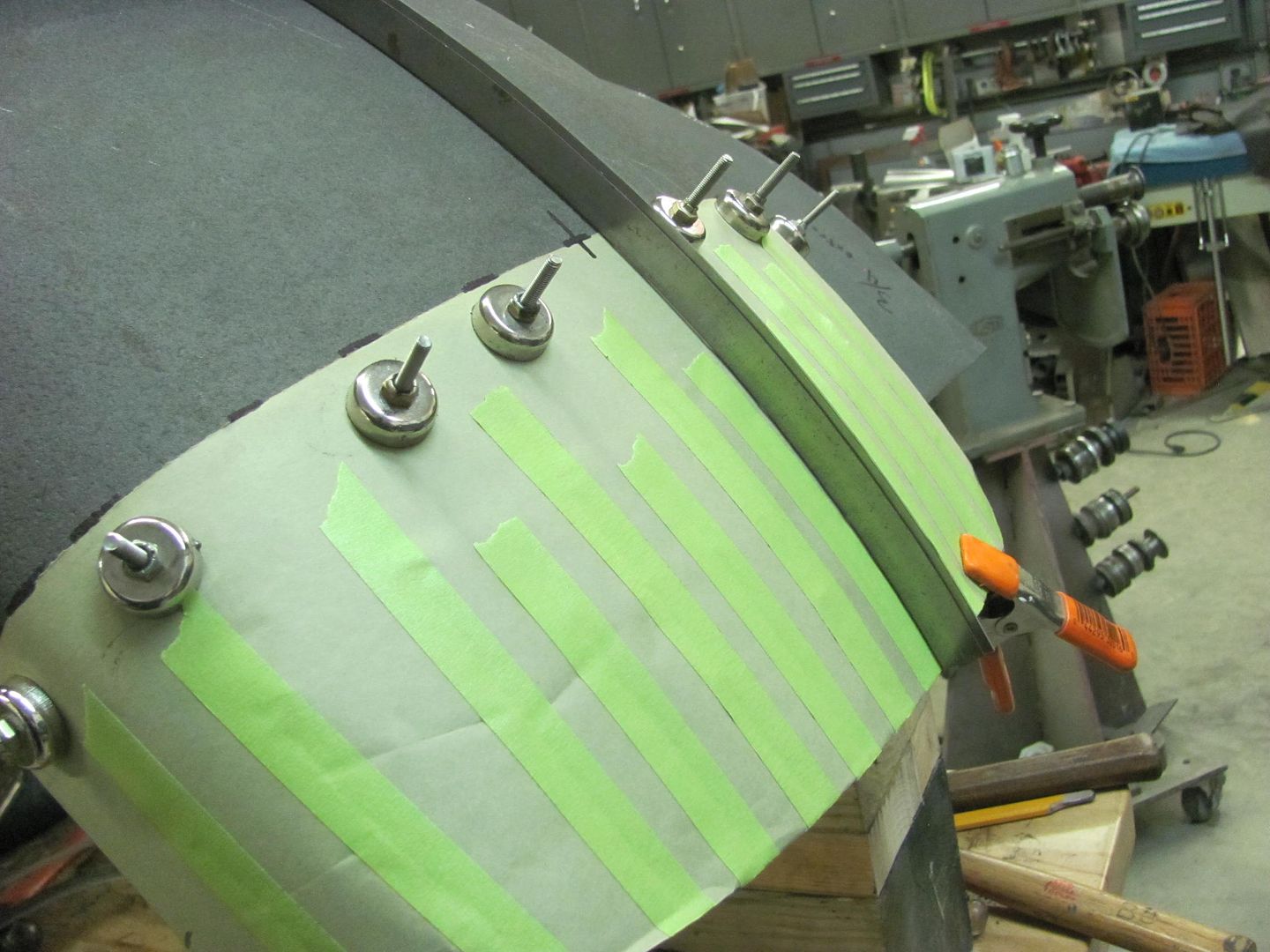
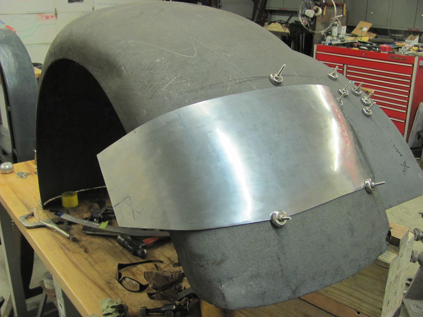
    Now with an accurate pattern, we can use the template on the new inner fender..
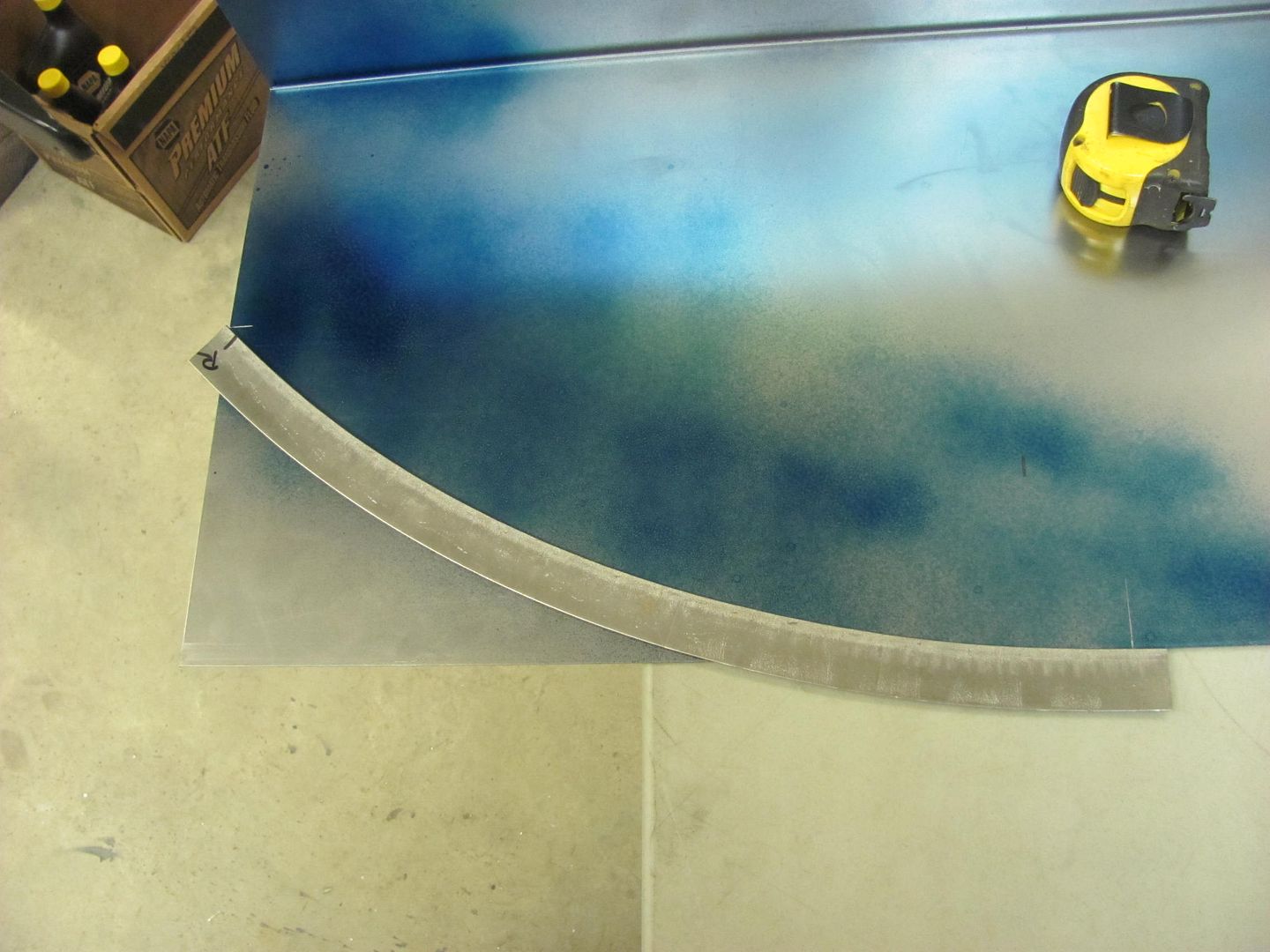
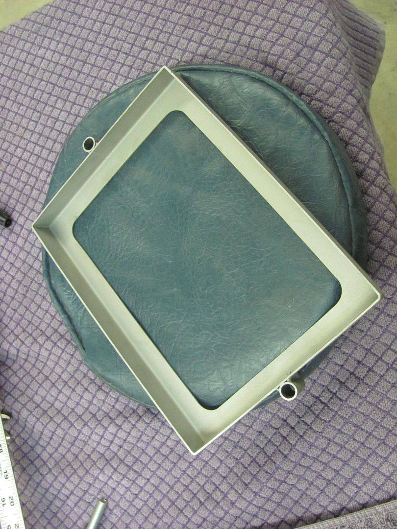
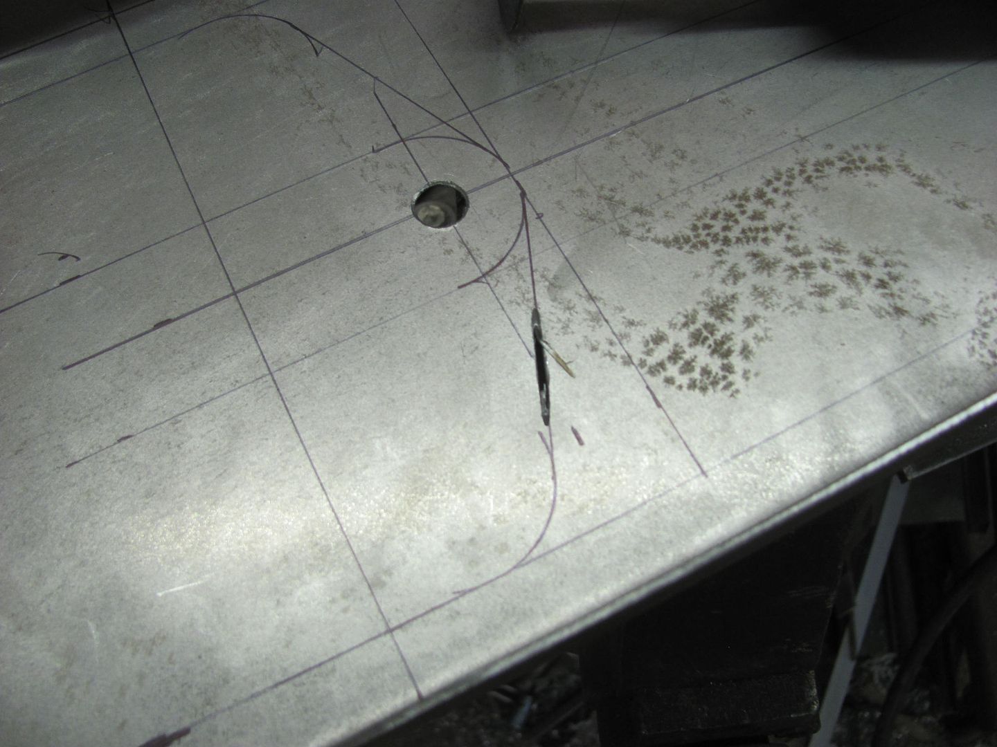


    All trimmed...


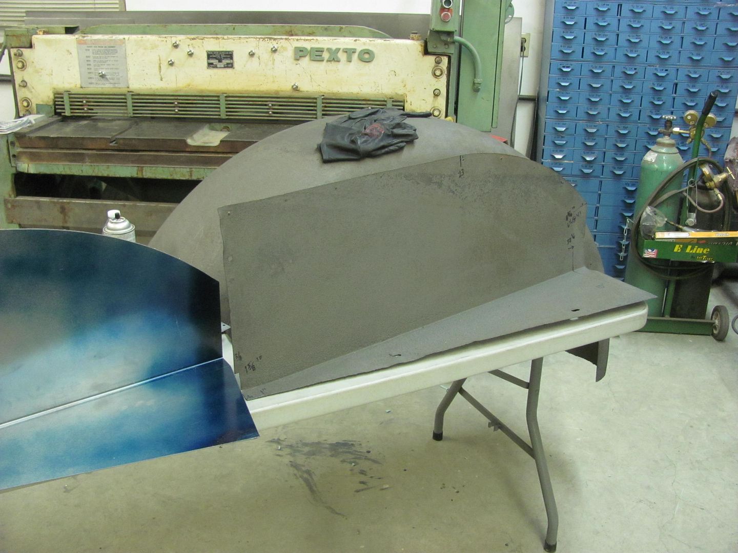
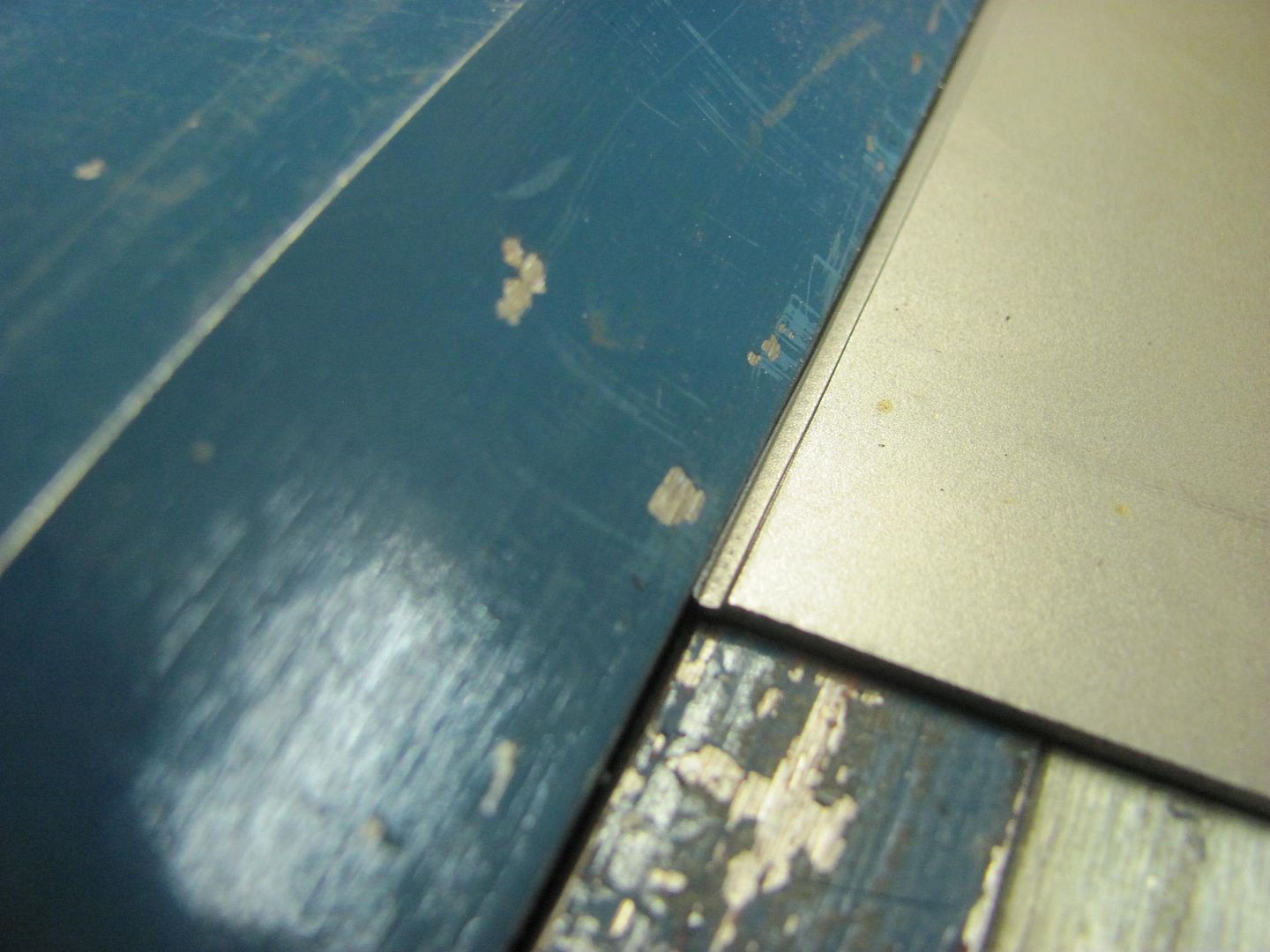
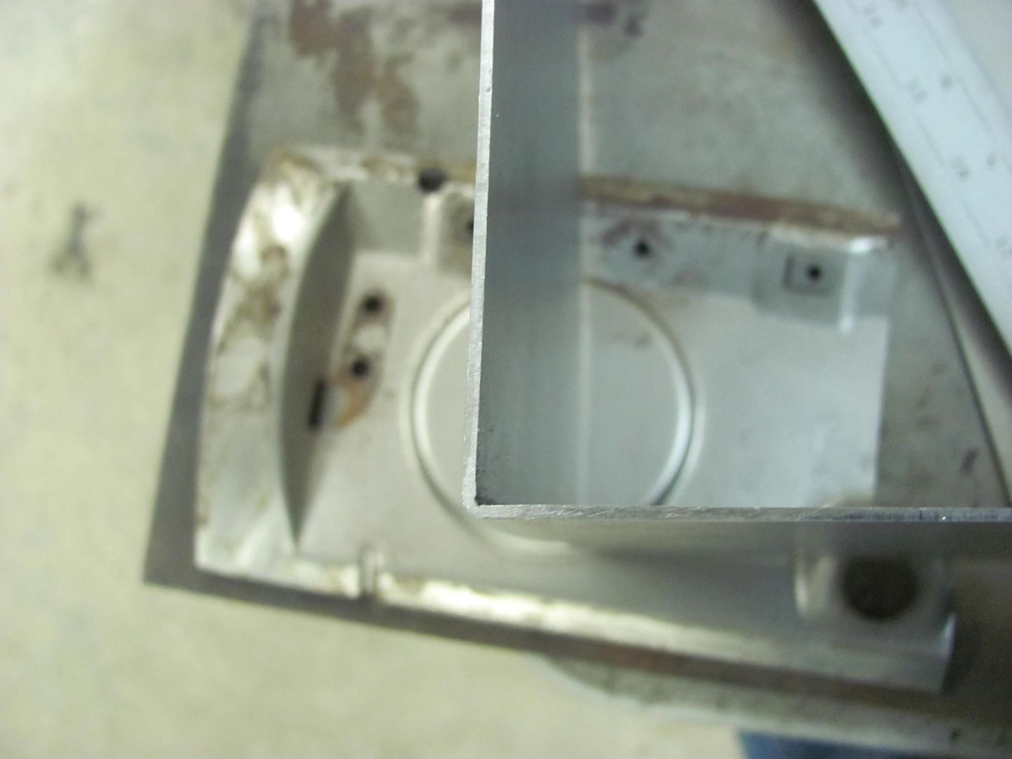
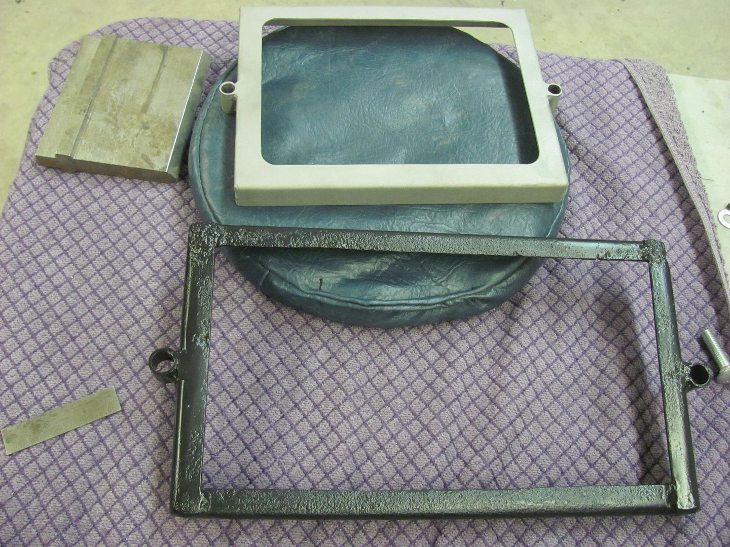
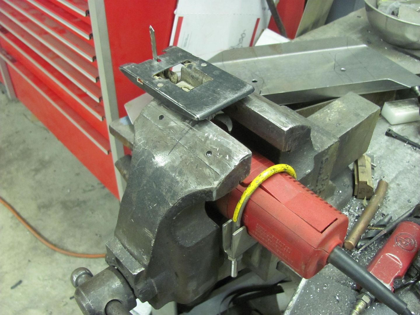
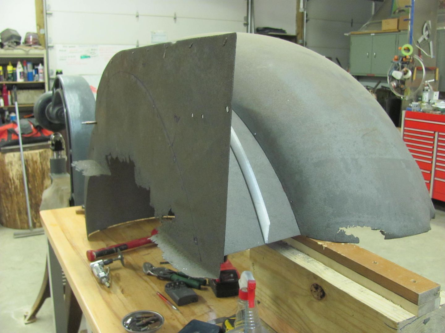
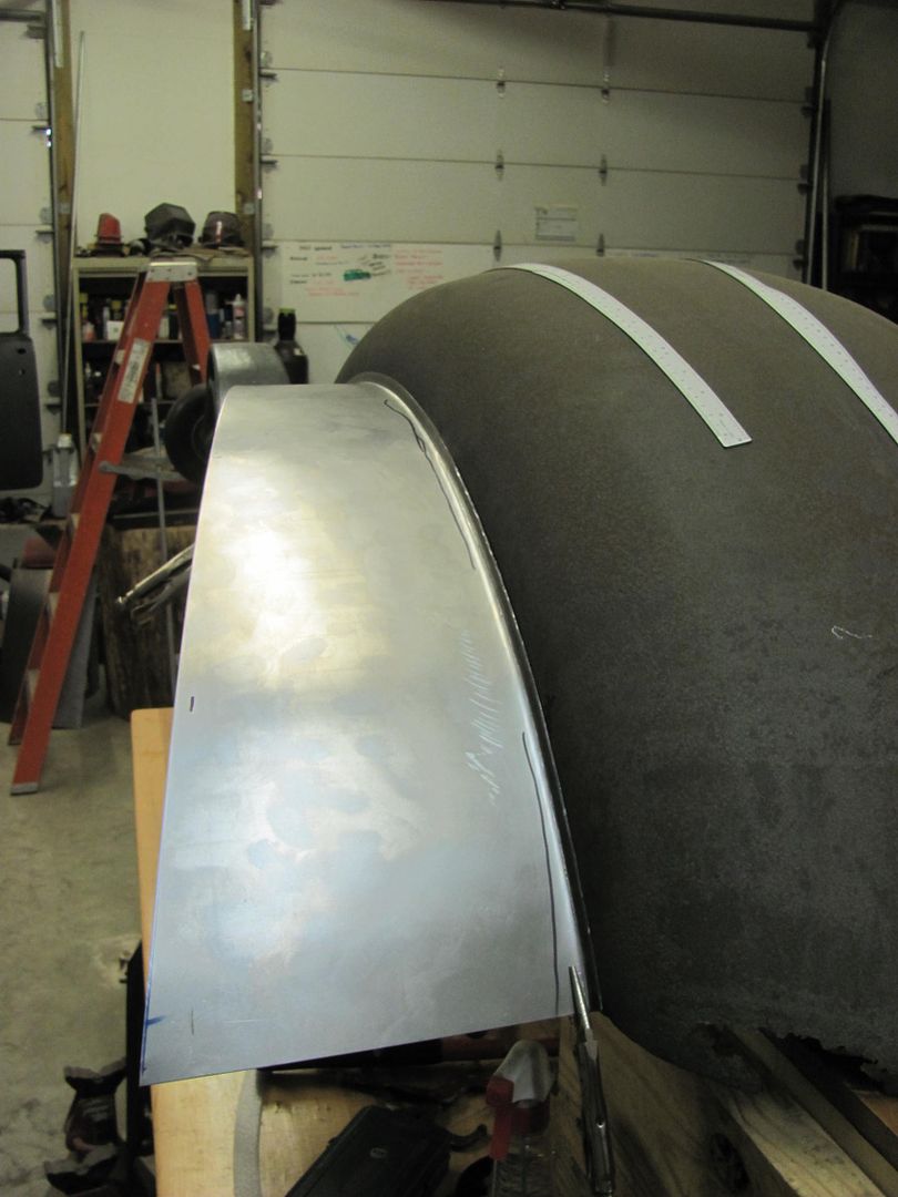
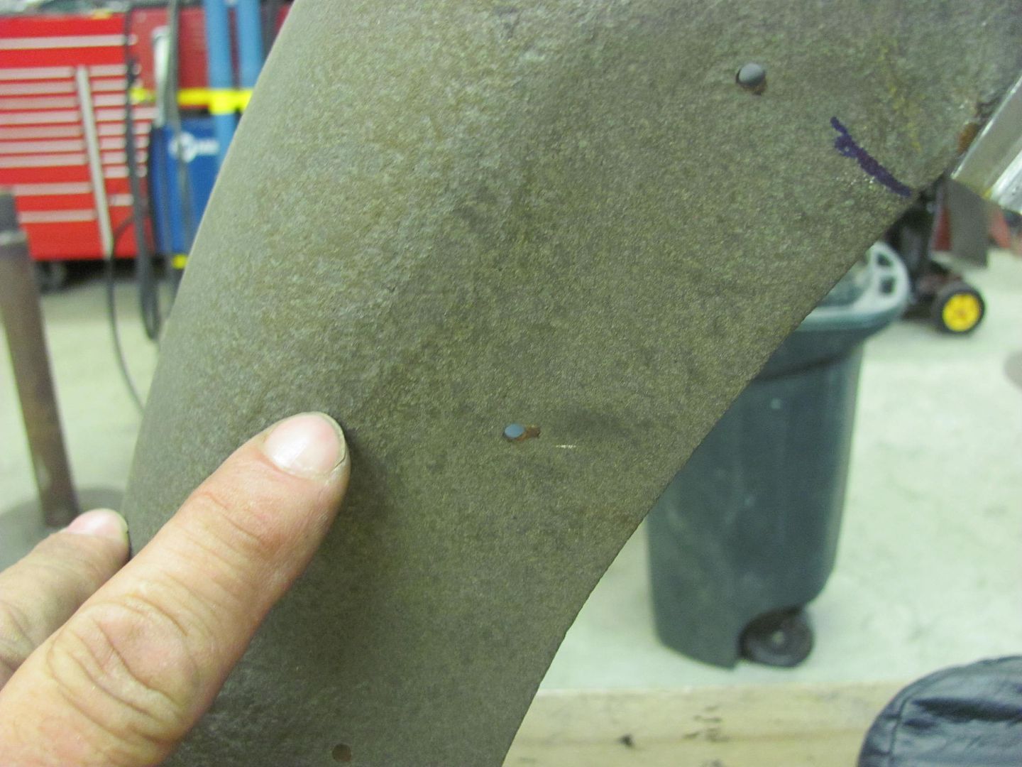
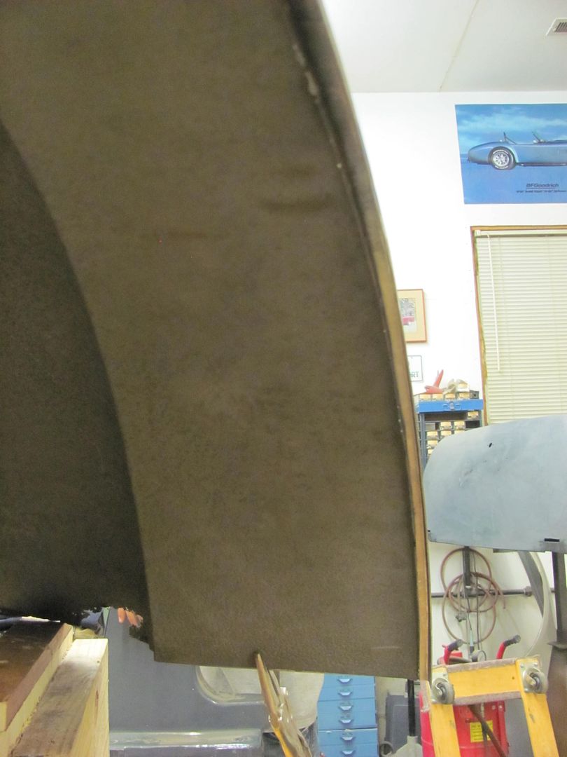
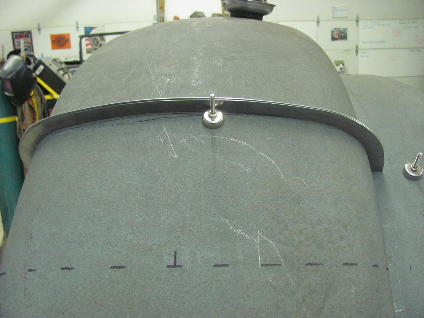
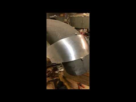
    With the new clamped to the old, we can see what the years of abuse has done..


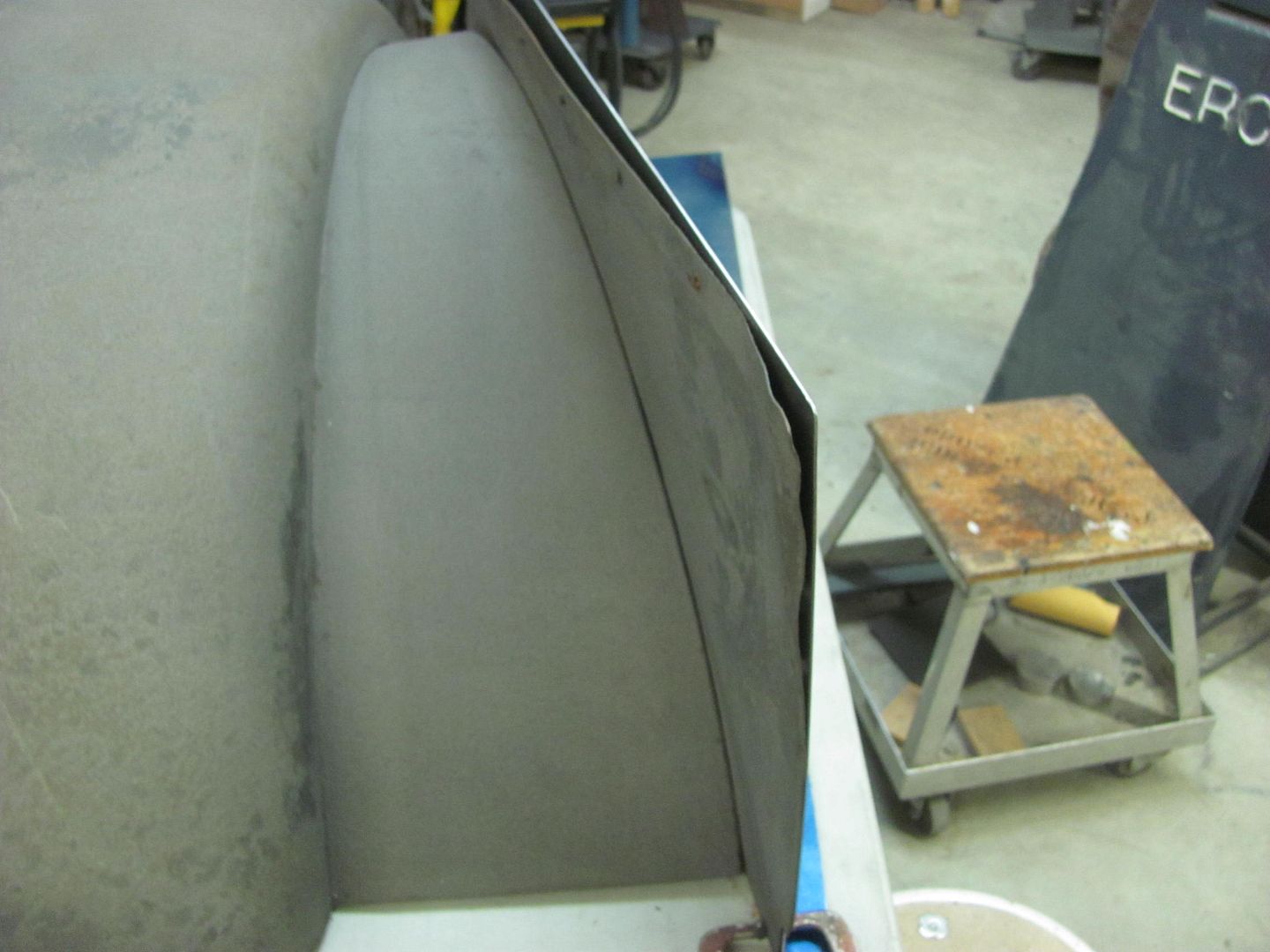
    One down, one to go..


    Robert


    Instagram @ mccartney_paint_and_custom


    MP&C Youtube Channel

  • #2
    Today we got the second inner fender cut out, and took them both over for a test fit on the truck


    The driver's side has a bolting plate in the middle of the frame for the steering box, so a relief notch was in order...


    ....as well as a bit of trimming for some clearance so that the paint won't be chipped off on the first test drive. The fabrication of these parts are done, and we should pick up the new Tommasini Wheeling Machine this coming weekend so we can get started on the fender patches..


    Robert


    Instagram @ mccartney_paint_and_custom


    MP&C Youtube Channel

    Comment


    • #3
      LOVE the truck and, as always, your magic applied to it. Maybe a build thread (or move this thread?)

      Dan

      Comment


      • #4
        Thanks Dan, but my only job here is to fix the fenders so I didn't see this as a project vehicle to show a start to finish. If the mods feel otherwise, change accordingly..
        Robert


        Instagram @ mccartney_paint_and_custom


        MP&C Youtube Channel

        Comment


        • #5
          Neat project either way.

          Dan

          Comment


          • #6
            Had a question about placement of the thinning groove, so I thought I'd post the results of the test sample...


            Originally posted by WoodsTruck
            Question about the use of your tipping die for bending a straight line.

            What would happen if you made the divot on the back side of the bend instead of the front? I realize you are referring to this as "thinning" the metal, but aren't you actually forging it in a sense since you aren't actually removing metal but compacting it primarily? To my inexperience it would seem that a tight bend could be made without the resulting trough if the tipping die was used on the backside of the bend.

            Fantastic work though, wish I had half the knowledge and tools to do that stuff. I'm a graduate of the BFH school.

            Here's the test from tonight. The 16 ga thickness measured out to about .057, at the "thinning" groove it was .053, so we lost about .004 in thickness, or less than 10%. Put the thinning groove on the outside for this bend, it tended to stretch the deformity back out again where it looks like it could be more readily cleaned up with a file..


            So where the bending process allowed the groove to stretch back out....


            ...it also gave us a wider radius than when the thinning was placed on the inside of the bend...


            So I'd say to use placement based on if a tighter radius is needed or whether you need it dressed out
            Robert


            Instagram @ mccartney_paint_and_custom


            MP&C Youtube Channel

            Comment


            • #7
              John's getting ready for engine start ceremonies, so I guess I need to get off my duff here. To help out in that regard, next we'll fabricate the battery tray which I don't believe came with the truck when John got it. Here's the best we have for a pattern:


              The hold down bracket for the prescribed Group 4 battery was with the truck, so we did some test fitting with the inner fender in place. It is a bit cramped for space, and John expressed concern of the availability of the Group 4 battery. Most local sources only carry the Group 1 in stock, which would also be a better fit.. So out with the old...


              I did miss getting in the flat pictures, but here is the freshly folded and welded hold down bracket for the new battery size.


              All trimmed and prepped for paint..


              Comparing the new to the old...


              Next will be the new battery tray.
              Robert


              Instagram @ mccartney_paint_and_custom


              MP&C Youtube Channel

              Comment


              • #8
                SORCERY !!! no other way to descibe it.

                Comment


                • #9
                  Haha! Thanks!


                  ...and now for the battery tray, shown here cut to size and sides folded up...


                  For the end folds, the cut was started using a .035 cutoff wheel..


                  ...and our trusty jig saw again...


                  Both ends complete, and frame holes have been piloted. Once checked to the hole spacing on the frame they can be drilled out for the 3/8 bolts.


                  Robert


                  Instagram @ mccartney_paint_and_custom


                  MP&C Youtube Channel

                  Comment


                  • #10
                    More progress on the Biederman fenders.. With Kyle on vacation I was shorthanded in the shop so John (the owner) came by and lent a hand.

                    First step was to remove the inner fender to see what we had to work with, added some 1/8 holes to use later for clecos in putting things back together..


                    The front of the fender bolts to the bumper filler panel, and the rear bolts to the running board. These have a difference in height of 13-3/4, so some blocks were screwed together to hold the fender in correct placement while we worked.


                    The inner is getting replaced so the spot welds were ground out for removal.


                    Once removed, we found more pitting and damage than we originally thought was there, so now lets make this new as well..


                    New piece is cut out and the Wheeling machine with the go kart slick is used to add the correct radius..


                    Then the flange bend line is marked/thinned using a tipping die in the Lennox like we did for the inner panels we made..


                    Then a tipping die and Skateboard wheel in the bead roller is used to make the initial fold on the marked line


                    and finished up with a Step die so we could use it as a backstop


                    The Erco 1447 with stretcher dies was used to stretch the flange in between tipping sessions. All done, matches the fender contour, we'll get the other side folded down next time..


                    Last edited by MP&C; August 13, 2016, 08:44 PM.
                    Robert


                    Instagram @ mccartney_paint_and_custom


                    MP&C Youtube Channel

                    Comment


                    • #11
                      How did you come about using that go kart slick as the upper wheel?

                      Comment


                      • #12
                        The half-flat go kart slick doesn't form the panel in two directions like a steel upper wheel would. It pushes the panel around the crown of the lower anvil but leave it flat lengthwise. Makes one heck of a "slip roll" if you wanted to make some rocker panels.
                        Robert


                        Instagram @ mccartney_paint_and_custom


                        MP&C Youtube Channel

                        Comment


                        • #13

                          Here's a quick video to show how the radius for the filler panel was done..


                          With the flanges turned both directions....


                          Looking at the rear of the fender that was adjacent to the cab, we found flat areas that seem to indicate some rubbing was occurring. So while we were fabricating the filler panel, we added about 1/8" to shove the fender outward away from the cab.


                          Robert


                          Instagram @ mccartney_paint_and_custom


                          MP&C Youtube Channel

                          Comment


                          • #14
                            Some more work on the Biederman fenders..

                            A paper pattern was taken from the front of the fender to use as a guide to cut out the new piece from 16 ga cold rolled steel.


                            Some 19 gauge was hemmed flat and the Erco kick shrinker used to make profile templates for the horizontal and vertical directions..


                            The initial shape was added with a blocking hammer and shot bag, and finished on the Wheeling Machine..


                            Getting close....


                            This video shows the progress so far, as well as the rust on the leading edge we're repairing..

                            Robert


                            Instagram @ mccartney_paint_and_custom


                            MP&C Youtube Channel

                            Comment


                            • #15
                              Fender filler panel Number 2 is complete:


                              Fender patch is getting closer...


                              Robert


                              Instagram @ mccartney_paint_and_custom


                              MP&C Youtube Channel

                              Comment

                              Working...
                              X